Paper board stack separating device

A separation device and cardboard technology, applied in the field of carton or carton processing system, can solve problems such as damage to printed cardboard, difficulty in continuing to convey, slipping, etc.

Pending Publication Date: 2019-03-26
安徽华艺包装科技有限公司
View PDF0 Cites 5 Cited by
  • Summary
  • Abstract
  • Description
  • Claims
  • Application Information

AI Technical Summary

Problems solved by technology

The printed cardboards printed by the printing equipment are transferred to the folding box equipment in stacks. The feeding end of the folding box equipment also places the printed cardboards in stacks, and usually the printed cardboards are stacked with the printing side down. The bottom printing cardboard is first transferred to the conveyor belt and conveyed downstream in turn. Because the printing ink is not completely dry or there is a certain amount of moisture on the cardboard and the pressure of the cardboard stack is easy to bond between the cardboard, the conveyor belt and the bottom printing cardboard The friction between the printed smooth surface of the cardboard is small, and the friction between the raw cardboard rough surface of the bottom printed cardboard and the printed cardboard above it is relatively large, so slipping often occurs between the conveyor belt and the bottom printed cardboard This leads to difficulty in conveying, which seriously affects the processing efficiency; more seriously, even if the printed cardboard reaches the conveyor belt and can be transported downstream with the movement of the conveyor belt, the posture of the initial position of the printed cardboard cannot meet the requirements. The base edge of the cardboard will be inclined, which will make it difficult to continue conveying downstream, and even cause damage to the printed cardboard

Method used


Image

  • Paper board stack separating device
  • Paper board stack separating device
  • Paper board stack separating device

Examples


Embodiment Construction

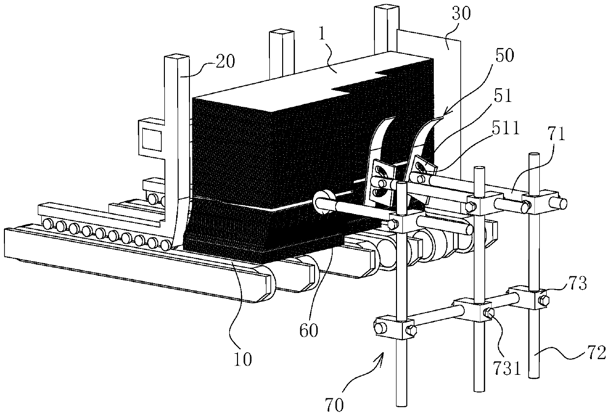
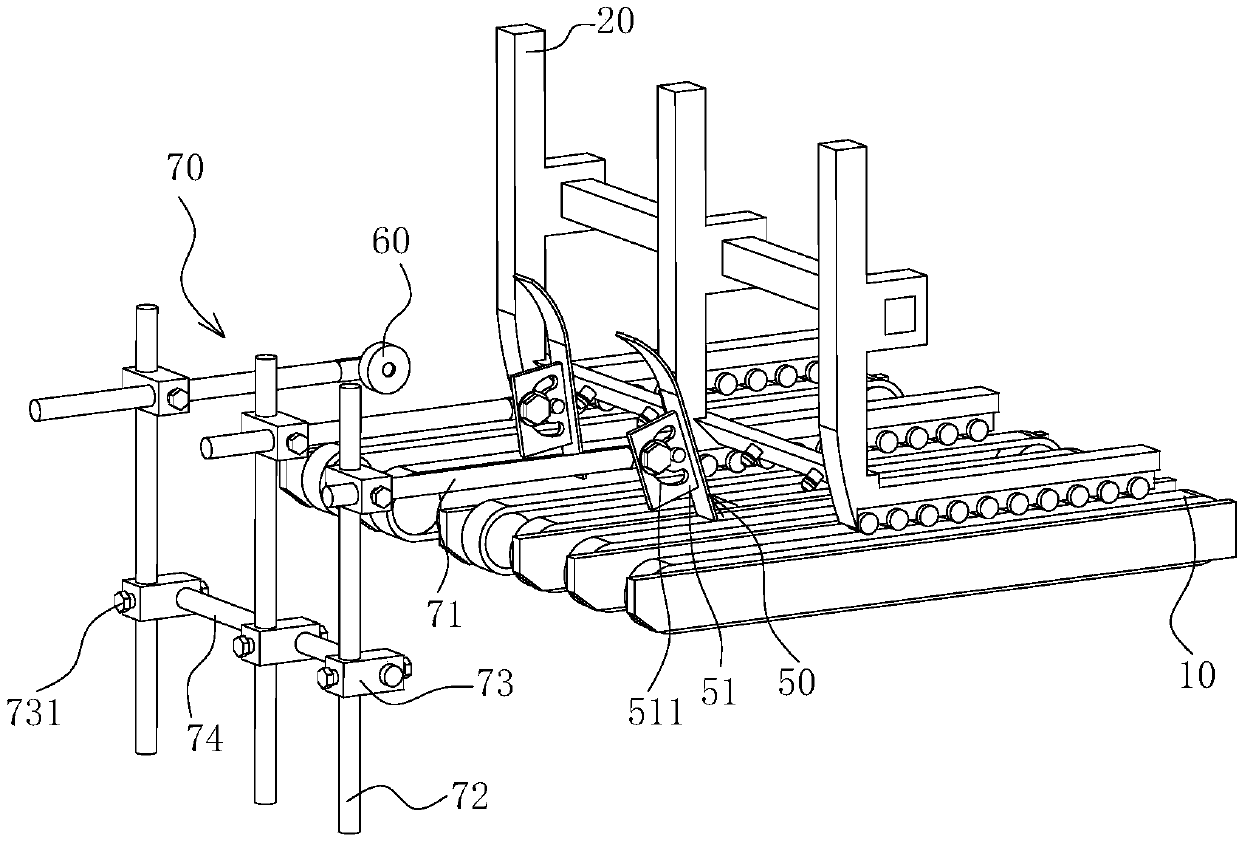
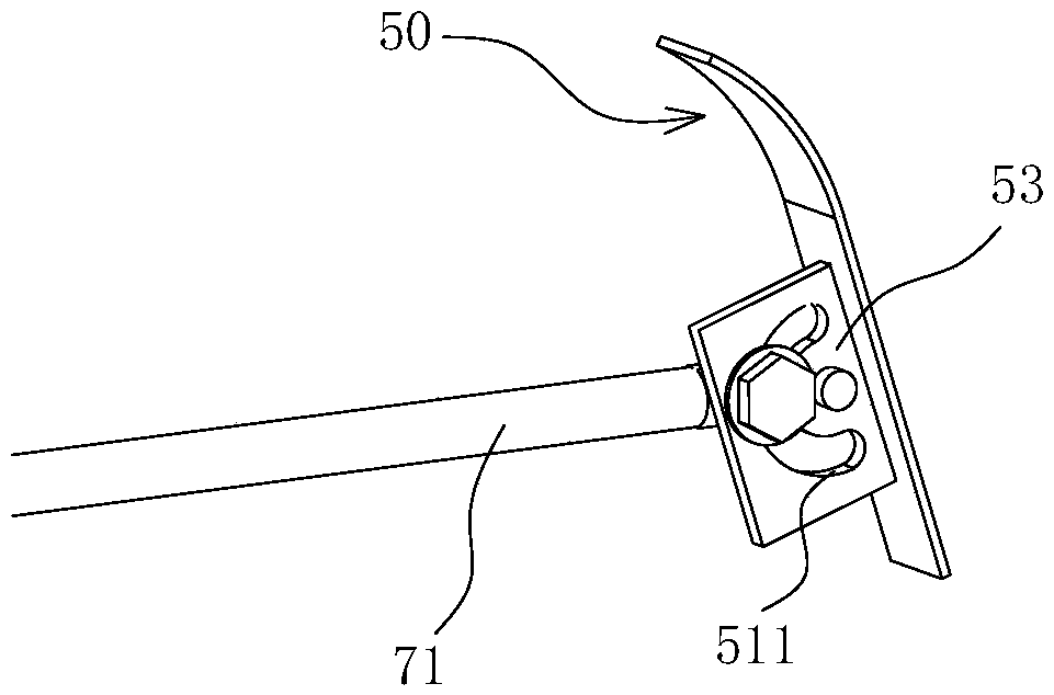
[0009] See attached figure 1 , 2 , 3, a cardboard bundle 1 separation device, including a baffle 20 located at the feed end of the conveyor belt 10, the distance between the lower edge of the vertically arranged baffle 20 and the conveyor belt 10 is greater than the thickness of one cardboard and less than two cardboards thickness, the lower part of the baffle 20 transitions from back to front and from top to bottom with an arc-shaped curved surface, and a pusher 50 is arranged behind the baffle 20, and the lower part of the plate or rod-shaped pusher 50 is from top to bottom. An oblique arrangement from back to front.

[0010] In the above solution, the cardboards are placed in stacks on the feeding end of the conveyor belt 10 against the baffle 20, and the cardboards on the lower layer are misaligned along the obliquely arranged pusher 50 and the arc-shaped curved surface of the baffle 20. Stacking, the dislocation process of the cardboards can eliminate the adhesive force...


PUM


Abstract

The invention discloses a paper board stack separating device. The device comprises baffles located at the feed ends of conveying belts. The intervals between the lower edges of the vertically-arranged baffles and the conveying belts are larger than the thickness of one paper board and smaller than the thicknesses of two paper boards, the lower portions of the baffles are in transition from rear to front and from top to bottom as arc curved surfaces, pushing parts are arranged behind the baffles, and the lower portions of the platy or rodlike pushing parts are inclined from top to bottom and from rear to front. Paper boards are put at the feed ends of the conveying belts in a stacked manner and abut against the baffles, the paper boards on the lower layers are stacked in a staggered manneralong the inclined pushing parts and the arc curved surfaces of the baffles, and the paper boards on the lowest layer run forwards along with the conveying belts to pass through the lower edges of the baffles. The intervals between the lower edges of the baffles and the conveying belts are larger than the thickness of one paper board and smaller than the thicknesses of two paper boards, only onepaper board passes through the lower edges of the baffles every time, and the printing paper boards are stably and reliably taken out of a paper board stack one by one from bottom to top and conveyeddownstream.

Description

technical field [0001] The present invention relates to a carton or carton processing system, in particular to conveying the separation of raw cardboard packs for the manufacture of cartons or cartons. Background technique [0002] The processing of packaging boxes or boxes used as product packaging mainly includes cardboard printing and glued folding boxes for printed cardboard. The above two main processes are completed by printing equipment and folding box equipment respectively. The printed cardboards printed by the printing equipment are transferred to the folding box equipment in stacks. The feeding end of the folding box equipment also places the printed cardboards in stacks, and usually the printed cardboards are stacked with the printing side down. The bottom printing cardboard is first transferred to the conveyor belt and conveyed downstream in turn. Because the printing ink is not completely dry or there is a certain amount of moisture on the cardboard and the pre...

Claims


Application Information

Patent Timeline
Patent Type & Authority Applications(China)
IPC IPC(8): B65H3/04B65H3/46B31B50/06
CPCB65H3/042B31B50/06B65H3/46B65H2701/176
Inventor 李朝英
Owner 安徽华艺包装科技有限公司
Why Eureka
Try Eureka