Method for fixing concrete column beam formwork chamfering strips

A technology of concrete columns and fixing methods, applied in covering/lining, construction, building construction, etc., can solve problems affecting project progress, slow construction speed, and difficult nail size, so as to reduce the comprehensive cost of construction, improve operating efficiency, The effect of ensuring the quality of reinforcement

Inactive Publication Date: 2019-03-26
MCC5 GROUP CORP SHANGHAI
View PDF6 Cites 1 Cited by
  • Summary
  • Abstract
  • Description
  • Claims
  • Application Information

AI Technical Summary

Problems solved by technology

The use of double-sided adhesive will cause the chamfering strip to displace, deform or break during the concrete vibration process, which will affect the final forming effect and also affect the repeated use of the chamfering strip
When using nails, the size of the nails is difficult to control, the chamfering strips will be damaged during the hammering process, the distance between the chamfering strips and the formwork nails will not be completely close, and the depth of the nail into the formwork will cause different displacements, deformations or Broken, the four corners of the column formwork are difficult to fix, and the construction speed is slow to fix with nails, which affects the progress of the project
[0006] Therefore there are above-mentioned inconveniences and problems in the plastic material of the known concrete column beam formwork chamfering strip and the method for fixing with steel nails

Method used


Image

  • Method for fixing concrete column beam formwork chamfering strips
  • Method for fixing concrete column beam formwork chamfering strips

Examples


Embodiment 1

[0033] Concrete column beam formwork chamfering strip fixing method of the present invention comprises the following steps:

[0034] a. Prepare concrete column beam formwork, air nail gun and air nail

[0035] Concrete column and beam formwork is made of bamboo plywood, and commercially available air nail guns are purchased, which are equipped with F25 air nails; in this embodiment, air nail gun ST60 is used, and F25 air nails are used. The thickness of the bamboo plywood of the column and beam formwork is 18mm.

[0036] b. Prefabricated chamfering strips

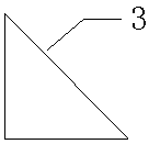
[0037] figure 2 It is a schematic cross-sectional view of a chamfered strip according to an embodiment of the present invention. Bamboo plywood is used as material to prefabricate chamfering strips. The chamfering strips are long and the length is determined according to the needs of the concrete column and beam formwork. The corners are all 45°, and the thickness of the bamboo plywood for the chamfering strips is 7mm....

Embodiment 2

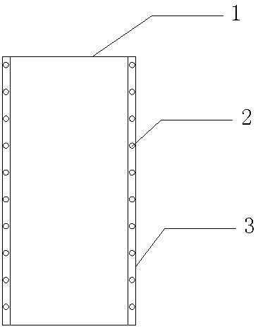
[0041] This embodiment illustrates that the chamfering strips in the concrete column formwork are fixed, and the technical measures for preparing the concrete column beam formwork, air nail gun and air nails, and the prefabricated chamfering strips are the same as in Example 1. The frame-shaped concrete column formwork in the vertical state is produced by the conventional method, and the four prefabricated chamfering strips are vertically placed on the four corners of the frame-shaped concrete column formwork, so that the right angles formed by the four-corner formwork of the frame-shaped concrete column formwork and the angle of the chamfering strips For right-angle stacking, use an air nail gun with F25 air nails, and fix the chamfered strips in the concrete column formwork with several air nails. The driving positions of the plurality of air nails are in a straight line state, and the driving distance between two adjacent air nails of the plurality of air nails is 100mm.

...


PUM


Abstract

A method for fixing concrete column beam formwork chamfering strips comprises the steps that a, concrete column beam formworks, a gas nail gun and gas nails are prepared; b, chamfering strips are prefabricated; c, the chamfering strips are fixed in the concrete beam formwork; d, and the chamfered strips are fixed in the concrete column formwork. The method for fixing the concrete column beam formwork chamfering strips has the advantages that the gas nail gun is more economical than a concrete column beam chamfering machine in price, a chamfering strip device is simple in structure, good in stability and convenient to make, the reinforcing quality and speed and turnover times of the chamfering strips are ensured, concrete members are well formed, the fixed time period of the chamfering strips can be arranged flexibly, the operating efficiency is greatly improved, and the comprehensive cost of construction is reduced.

Description

technical field [0001] The invention relates to a concrete column beam formwork chamfering strip, in particular to a method for fixing the concrete column beam formwork chamfering strip. Background technique [0002] Concrete chamfering strips are mainly used for decoration, modeling, safety protection and standard lines of inner wall corners of industrial plants, civil buildings, commercial buildings, etc., especially for large-scale fair-faced concrete pouring process projects. [0003] Chinese patent CN204609163U disclosed a chamfering strip for construction on September 2, 2015, wherein the chamfering strip is a long strip with an L-shaped cross section, and its corners are arc-shaped, and the arc-shaped sides meet the right-angled sides The place is an arc surface, and the material used is wood. But the chamfering strip in its technical scheme is fixed on the wall with steel nails during installation, because one side of the chamfering strip is too thin and can be dama...

Claims


Application Information

Patent Timeline
Patent Type & Authority Applications(China)
IPC IPC(8): E04F13/06
CPCE04F13/06E04F2013/063
Inventor 王亮张隐李凯歌徐超
Owner MCC5 GROUP CORP SHANGHAI
Why Eureka
Try Eureka