Engine efficient axial rotation driving mechanism

A technology of axial rotation and drive mechanism, applied in the direction of machines/engines, mechanical equipment, etc., can solve the problems of friction between the roller and the wall, large friction force, energy loss, etc., to reduce operating vibration, reduce volume, and reduce energy The effect of loss

Pending Publication Date: 2019-03-26
苏州帕瓦麦斯动力有限公司
View PDF0 Cites 0 Cited by
  • Summary
  • Abstract
  • Description
  • Claims
  • Application Information

AI Technical Summary

Problems solved by technology

[0003] However, it is well known in the industry that there is actually a big problem in the known above-mentioned crankshaft-connecting rod transmission mechanism itself: there is always an angle when the force in the linear direction acting on the piston is transmitted to the crankshaft crank through the connecting rod, so that the crankshaft rotates What is always obtained in the direction is a decomposed force
Since the roller itself is in a state of high-speed rotation, it is not only difficult to change direction, but also will inevitably lead to friction between the roller and the wall, so this will actually cause a lot of wear on the roller
[0009] 3) The guide mechanism in the existing axial rotation drive mechanism adopts the cooperation form of the sliding guide sleeve and the guide post, and there is sliding friction between the sliding guide sleeve and the guide post, and the friction force is relatively large, which causes the mechanism to still exist during operation. A certain energy loss, which is obviously in urgent need of improvement for the mechanism whose main function is to improve energy conversion efficiency

Method used


Image

  • Engine efficient axial rotation driving mechanism
  • Engine efficient axial rotation driving mechanism
  • Engine efficient axial rotation driving mechanism

Examples


Embodiment 1

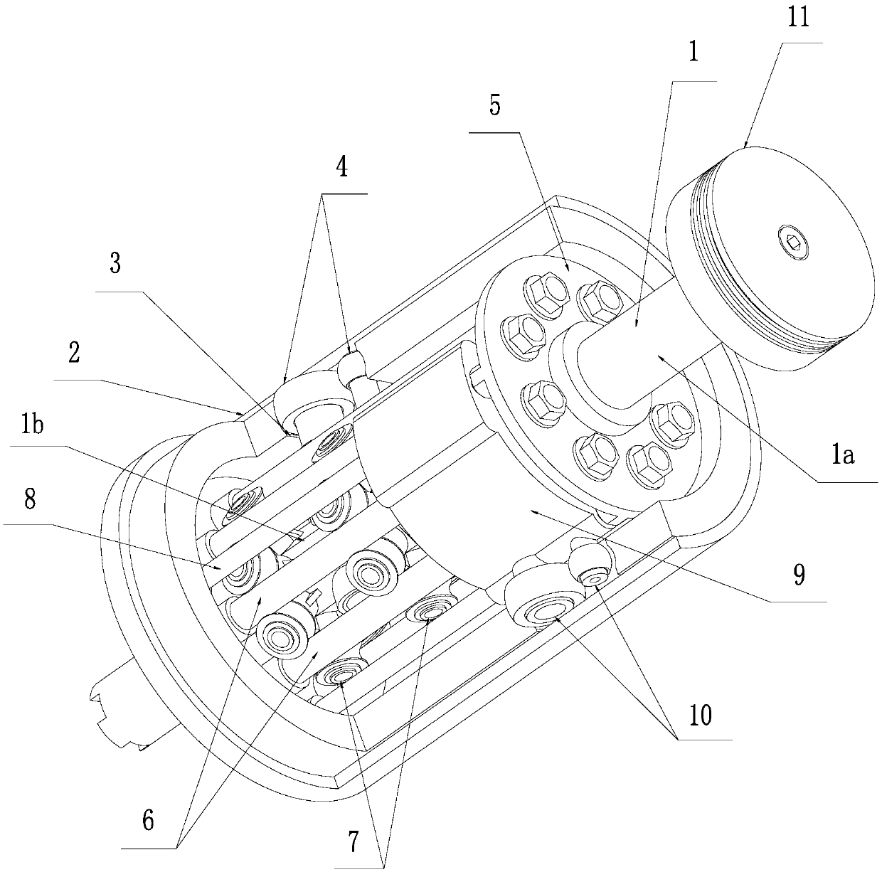
[0043] Example 1: Combining Figure 1~Figure 6 Shown is a specific embodiment of an engine high-efficiency axial rotation drive mechanism of the present invention.

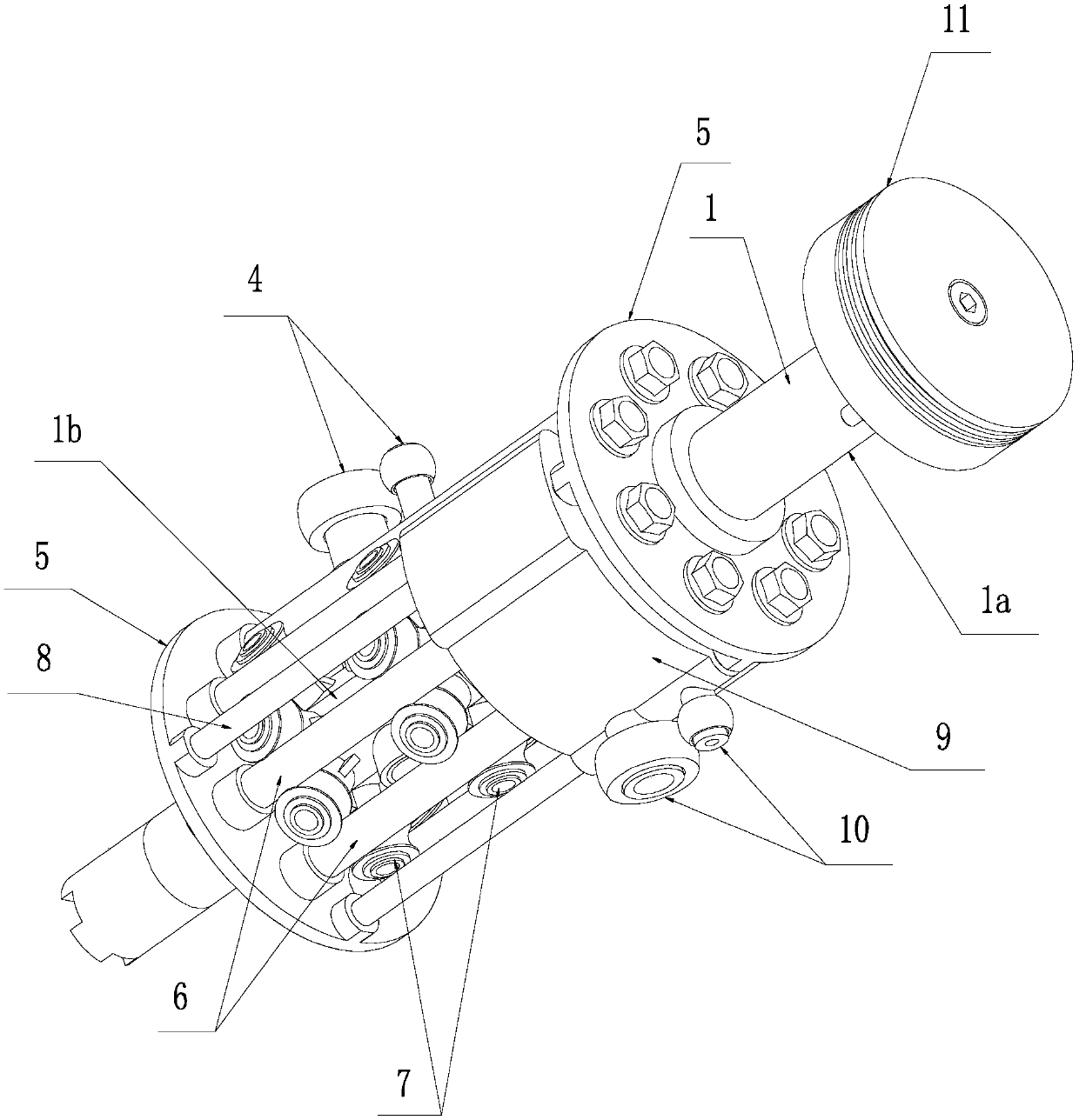
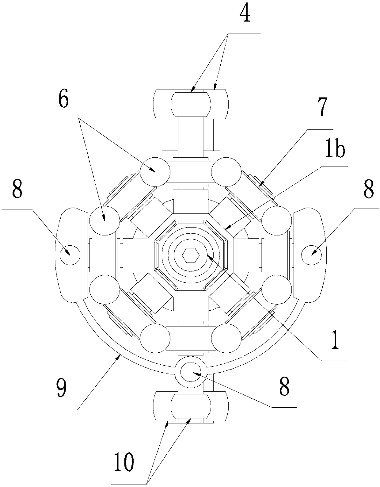
[0044] As in known designs, it has an axial movement member 1 , a rotational movement member 2 and a guide mechanism. In this embodiment, the rotary movement member 2 is a cylinder located on the periphery of the axial movement member 1, and the axial movement member 1 consists of a rod-shaped part 1a for connecting with the piston 11 and a rod-shaped part 1a fixed on the rod-shaped The seat body 1b on the part 1a is jointly formed, see Figure 4 shown. The guide mechanism includes two brackets 5 located on both sides of the seat body 1b, and the two brackets 5 are both made into a disc shape. One of the brackets 5 is provided with a perforation for the rod-shaped part 1a to pass through, specifically as figure 1 and figure 2 shown.

[0045] In this embodiment, an inclined closed-loop drive groove 3 is prov...

Embodiment 2

[0052] combine Figure 7~Figure 12 Shown is another specific embodiment of an engine high-efficiency axial rotation drive mechanism of the present invention.

[0053] Like Embodiment 1, it has an axial movement component 1, a rotation movement component 2 and a guide mechanism. In this embodiment, the rotary movement member 2 is also a cylinder located on the periphery of the axial movement member 1, and the axial movement member 1 is also composed of a rod-shaped part 1a for connecting with the piston 11 and a rod-shaped part 1a fixed on the rod-shaped The seat body 1b on the part 1a is jointly formed, see Figure 10 shown. The guide mechanism includes two brackets 5 located on both sides of the seat body 1b, and the two brackets 5 are also made into disc shapes. One of the brackets 5 is provided with a perforation for the rod-shaped part 1a to pass through, specifically as Figure 7 and Figure 8 shown.

[0054] The difference between this embodiment and Embodiment 1 i...


PUM


Abstract

The invention discloses an engine efficient axial rotation driving mechanism. A traditional engine axial rotation driving mechanism is improved; a driving groove on a traditional axial motion component is shifted onto a rotation motion component; a roller matched with the driving groove on the rotation motion component is shifted onto the axial motion component; through reversal design, the axialmotion component can be further optimized and reduced, and is manufactured by adopting light materials to reduce the weight and the operation vibration; and such high-strength materials as bearing steel are applied to the driving groove of the rotation motion component to improve the weight and the strength to achieve the overall mechanism balance between the weight and the strength, so that the mechanism energy loss is reduced, and the engine energy conversion efficiency is improved by one more level. Meanwhile, two sets of rollers acted on two side walls of the driving groove are designed toeliminate the reversing problem of single roller; a guide mechanism is optimized; and through cooperation between guide rollers and guide columns, the friction force is further reduced.

Description

technical field [0001] The invention relates to an engine high-efficiency axial rotation drive mechanism. Background technique [0002] The transmission device of the traditional engine mainly adopts the crankshaft-connecting rod transmission mechanism. The principle is that the axial force generated by the deflagration of the fuel applied to the piston to drive its linear motion is converted into a driving force through the connecting rod and its connecting structure with the crankshaft. The radial force of crankshaft rotation is very mature and widely used due to its simple structure and long-term continuous optimization and improvement. [0003] However, it is well known in the industry that there is actually a big problem in the known above-mentioned crankshaft-connecting rod transmission mechanism itself: there is always an angle when the force in the linear direction acting on the piston is transmitted to the crankshaft crank through the connecting rod, so that the cra...

Claims


Application Information

Patent Timeline
Patent Type & Authority Applications(China)
IPC IPC(8): F02B75/26
CPCF02B75/26
Inventor 陈维加
Owner 苏州帕瓦麦斯动力有限公司
Why Eureka
Try Eureka