A heater for an evenly heated air duct

A heater and air duct technology, applied in the field of electric heaters, can solve the problems of uneven heating effect and poor thermal conductivity.

Active Publication Date: 2020-10-23
JIANGSU JIUZHOU ELECTRIC APPLIANCE CO LTD
View PDF9 Cites 0 Cited by
  • Summary
  • Abstract
  • Description
  • Claims
  • Application Information

AI Technical Summary

Problems solved by technology

[0003] During the heating process, especially when the volume of the heater is large, the heat conduction effect of the air itself is poor, so only the part of the air that is in contact with the electric heating tube shell or the fin is heated, and a considerable part of the high-speed flowing air is not in contact with it. When the heat dissipation element is in contact, it can only be heated by the high-temperature hot air that has been heated around, so that the air discharged from the heater outlet contains multiple airflows of different temperatures, resulting in the disadvantage of uneven heating effect

Method used


Image

  • A heater for an evenly heated air duct
  • A heater for an evenly heated air duct
  • A heater for an evenly heated air duct

Examples


Embodiment Construction

[0029] The detailed description will be given below in conjunction with the drawings in the embodiments of the present invention.

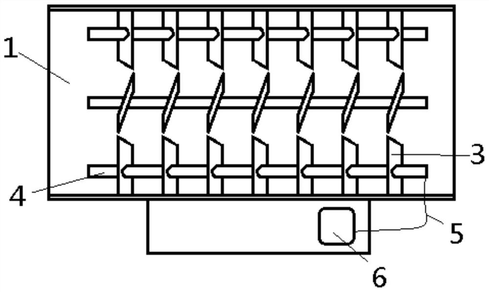
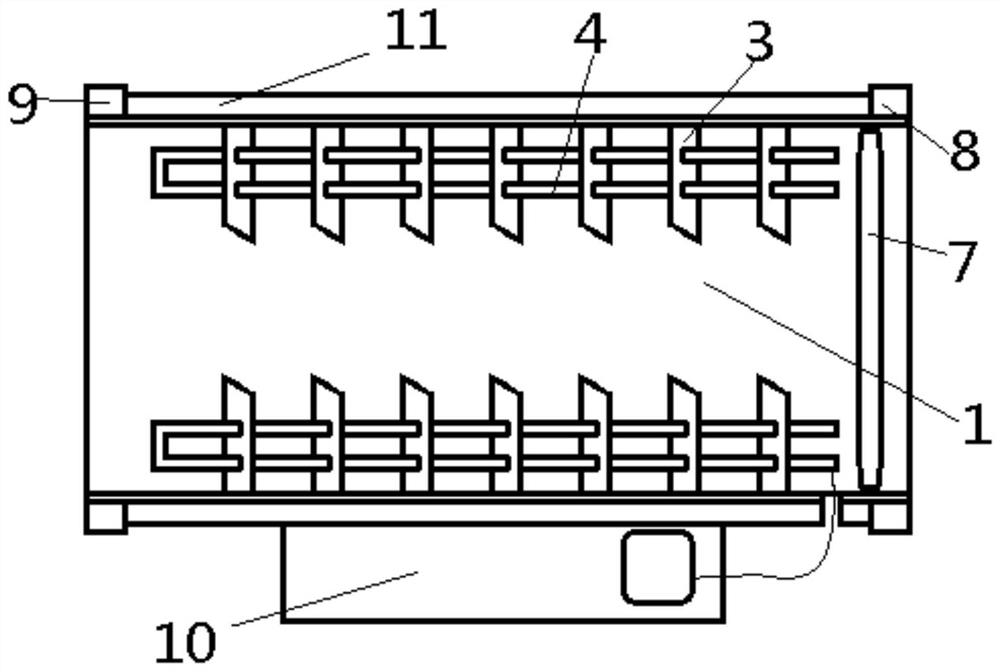
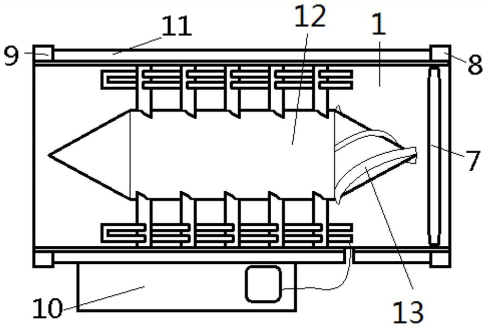
[0030] See figure 1 , A uniformly heated air duct heater, which mainly includes: a section of cylindrical air duct 1 arranged in a horizontal direction; the inner side wall of the air duct 1 is connected with several rows of heat dissipation fin groups arranged in the axial direction, each A row of radiating fins is composed of a number of fins 3 set parallel to each other, and each fin 3 has an inclination angle with the axis of the air duct 1 to form the blades of an axial fan in the air duct 1 The electric heating tube 4 runs through the center of each row of radiating fin groups, and each electric heating tube 4 is arranged parallel to the axis of the air duct 1; the inner side wall of the air duct 1 is penetrated with a wire hole corresponding to any end of each electric heating tube 4 , The wire hole is provided with wires 5 connected to the el...


PUM


Abstract

The invention relates to an electric heater, in particular to a heating-uniform air way heater. The heating-uniform air way heater mainly comprises a cylindrical air way provided with openings at twoends and horizontally arranged; a filter screen is arranged in the opening at any one end; multiple electric heating pipes are uniformly distributed in the air way in the peripheral direction; the electric heating pipes are arranged parallel to the axis of the air way; each electric heating pipe is fixedly connected with the inner side wall of the air way through fins; and all the fins in the airway are arranged in a blade shape of an axial flow fan. Under the effect of an air power module in the heater, air generates rotational currents in the heating process to achieve a more uniform heating effect.

Description

Technical field [0001] The invention relates to an electric heater, in particular to a heater for an air duct with uniform heating. Background technique [0002] Air duct electric heaters are used to heat the air in industrial ducts, air-conditioning ducts and air ducts of various industries to increase the temperature of the output air, and are generally inserted in the transverse openings of the ducts. According to the working temperature of the air duct, it is divided into low temperature, medium temperature and high temperature; according to the wind speed in the air duct, it is divided into low wind speed, medium wind speed and high wind speed. According to the structural characteristics, it is divided into electric heating tube shell heat dissipation and fin heat dissipation. [0003] During the heating process, especially when the heater has a large volume, due to the poor heat conduction effect of the air itself, only the part of the air in contact with the electric heatin...

Claims


Application Information

Patent Timeline
Patent Type & Authority Patents(China)
IPC IPC(8): F24H3/04F24H9/00F24H9/18
CPCF24H3/0405F24H9/0052F24H9/0063F24H9/0073F24H9/1863
Inventor 王彬葛文光陈玉林王俊蒋洲朱振亚
Owner JIANGSU JIUZHOU ELECTRIC APPLIANCE CO LTD
Why Eureka
Try Eureka