Automatic balloon pressurizing pump

A pressurized pump and balloon technology, applied in the direction of balloon catheters, catheters, etc., can solve problems such as inconvenience, and achieve the effect of improving safety and light weight

Inactive Publication Date: 2019-03-29
ZHEJIANG UNIV
View PDF10 Cites 6 Cited by
  • Summary
  • Abstract
  • Description
  • Claims
  • Application Information

AI Technical Summary

Problems solved by technology

[0005] The use of the balloon provides convenience for interventional surgery. However, in the current interventional surgery, the doctor needs to use a sterilized balloon inflation pump to manually inflate the balloon while holding the catheter with the other hand. , very inconvenient

Method used


Image

  • Automatic balloon pressurizing pump
  • Automatic balloon pressurizing pump
  • Automatic balloon pressurizing pump

Examples


Embodiment Construction

[0039] The present invention will be further described below according to accompanying drawing:

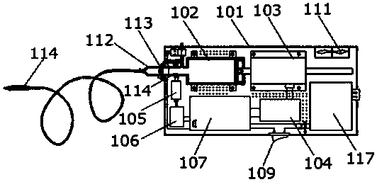
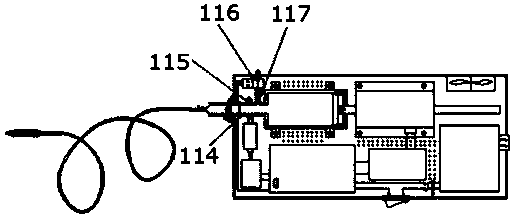
[0040] Such as figure 2 with image 3 As shown, an automatic balloon pressurizing pump includes a housing 101 with an inflation interface, and the housing 101 is provided with: an inflation cylinder 102 that is sealed and docked with the inflation interface; used to drive the piston in the inflation cylinder A linear motor 103 for motion; a linear motor driver 104 ; a pressure sensor 105 for detecting inflation pressure; a pressure sensor controller 106 ; and a controller 107 .

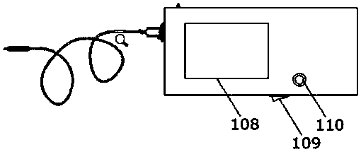
[0041] Such as figure 1 As shown, the housing of the present invention can be made of ABS engineering plastics, which is light in weight and not corroded, and provides installation space and protection for the rest of the parts. The casing 101 is provided with an inflation port, a vent port, a heat dissipation port, a charging port, and the like. At the same time, the housing 101 is also provided wit...


PUM


Abstract

The invention discloses an automatic balloon pressurizing pump including a shell provided with an air inflation port. The interior of the shell is provided with: an inflation cylinder in sealing buttjoint with the air inflation port; a driving mechanism for driving a piston in the inflation cylinder to move; a pressure sensor for detecting inflation pressure; and a controller, which receives thepressure signal from the pressure sensor and controls the driving mechanism according to the pressure sensor. By using the pressurizing pump, a medical balloon can be auto-inflated with air, so that complex operations of manual air inflation are avoided. The pressurizing pump has simple overall structure, is high in air inflation speed and efficiency, and can save air inflation time.

Description

technical field [0001] The invention relates to a medical device, in particular to an automatic balloon pressurizing pump. Background technique [0002] Inflatable balloons are very commonly used in interventional surgery, such as interventional balloons used in various lumens of the human body. By inflating the balloon, it can be used as an expansion support to expand the narrow lumen of the human body to achieve the purpose of treatment . [0003] The patent document whose publication number is CN107715282A discloses a medical dilatation balloon, including a push tube, an inner tube and an expandable balloon, the balloon is arranged at the distal end of the push tube, and the inner tube is arranged at the The push tube is inside and runs through the balloon, the push tube is a hollow structure, the proximal end of the push tube is provided with a connector, the end of the balloon far away from the push tube is welded to the inner tube, the balloon One end close to the pu...

Claims


Application Information

Patent Timeline
Patent Type & Authority Applications(China)
IPC IPC(8): A61M25/10
CPCA61M25/1018A61M25/10184
Inventor 刘震杰顾政须欣尹黎徐芳芳沈健
Owner ZHEJIANG UNIV
Why Eureka
Try Eureka