A dust removal device for v-method model casting equipment for foundry household appliances
A technology of casting equipment and dust removal device, which is applied in the field of dust removal device for V-method model casting equipment of foundry household appliances. efficiency effect
- Summary
- Abstract
- Description
- Claims
- Application Information
AI Technical Summary
Problems solved by technology
Method used
Image
Examples
Embodiment 1
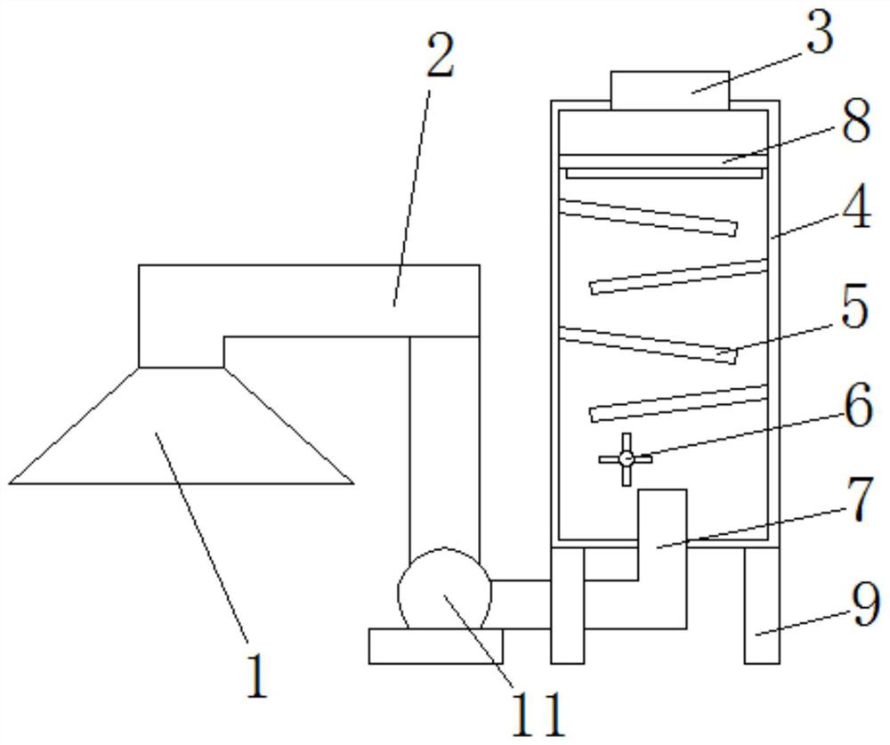
[0024] A dust removal device for V-method model casting equipment for foundry household appliances, including a dust removal chamber 4 and a dust collection fan 11, the intake end of the dust collection fan 11 is provided with an air intake pipe 2, and the front end of the air intake pipe 2 is provided with a dust collection Cover 1, the exhaust end of the other side of the dust suction fan 11 is provided with an exhaust pipe 7, the bottom of the exhaust pipe 7 communicates with the bottom of the dust removal chamber 4, and the upper end of the dust removal chamber 4 is provided with an exhaust port 3, The dust removal chamber 4 located at the bottom of the exhaust port 3 is provided with a fixedly connected first screen 8, the bottom of the first screen 8 is provided with evenly laid dust bags 14, and the bottom of the first screen 8 is provided with a second Two retaining nets 15, the first retaining net 8 and the second retaining net 15 are connected by a number of evenly di...
Embodiment 2
[0028] Same as embodiment 1 no longer restate, and embodiment difference is:
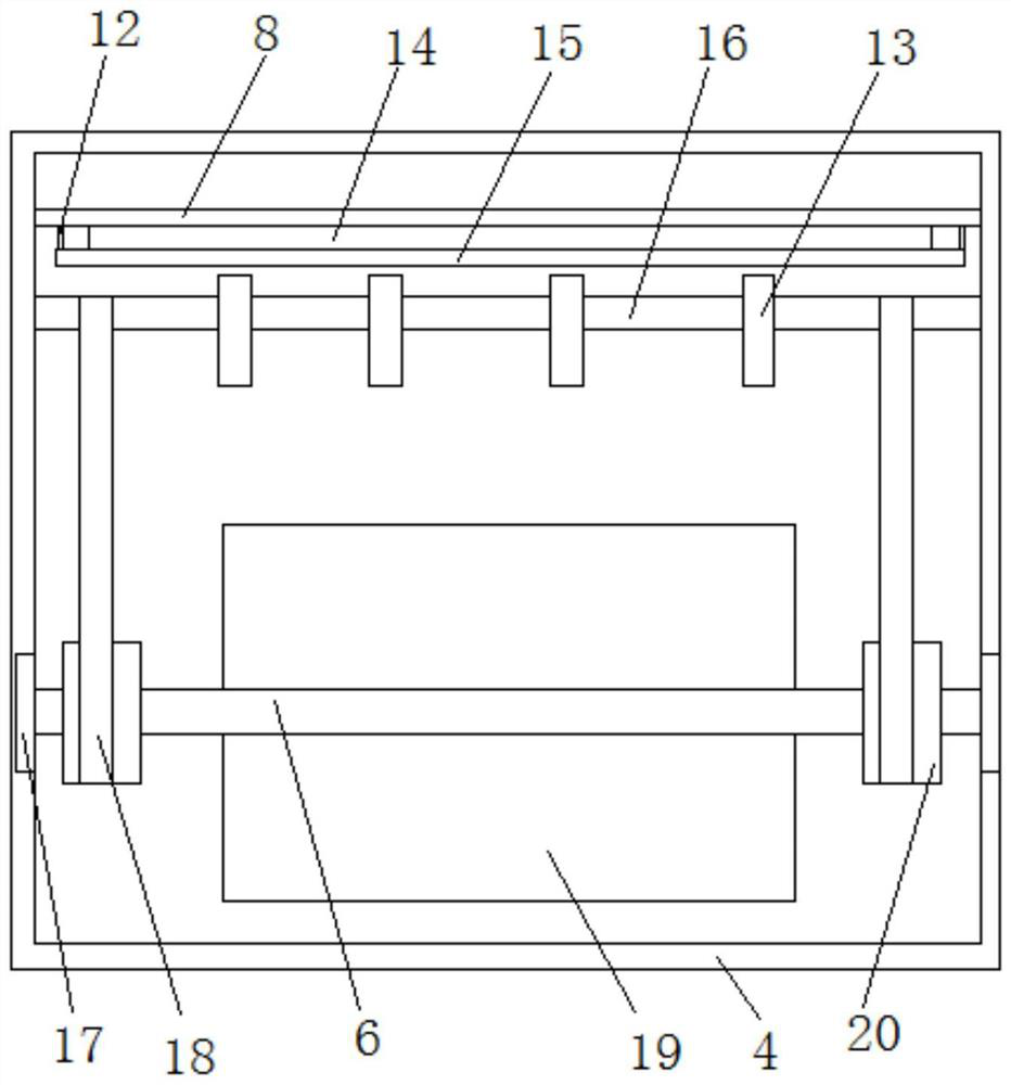
[0029] Preferably, the exhaust pipe 7 is arranged at the upper end of the bottom of the dust removal chamber 4, and the inner wall of the dust removal chamber 4 at the upper end of the exhaust pipe 7 is provided with symmetrically distributed springs 17, and the springs 17 pass through the first Connected by a connecting rod 6, the first connecting rod 6 located at the upper end of the exhaust pipe 7 is provided with a number of evenly distributed first fan blades 19, and the first connecting rod 6 located at both ends of the first fan blade 19 is provided with There are symmetrically distributed gears 20, and a movably connected connecting shaft 16 is provided in the dust removal chamber 4 at the bottom of the second screen 15, and a plurality of evenly distributed first cams 13 are arranged on the connecting shaft 16. The gears 20 is connected with the connecting shaft 16 by a chain 18.
[0030] ...
Embodiment 3
[0032] Same as embodiment 1 no longer restate, and embodiment difference is:
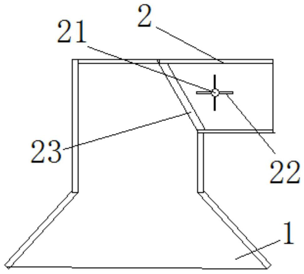
[0033] Preferably, the air intake pipe 2 located inside the dust collecting hood 1 is provided with an upwardly inclined dust screen 23 . The dust screen 23 performs preliminary filtration, which can effectively prevent the wind force of the dust suction fan 11 from absorbing larger particles into the dust removal chamber 4 and increase the load of the dust removal chamber 4 .
[0034] Further, the air intake pipe 2 located inside the dust screen 23 is provided with a second connecting rod 21 which is movably connected, and the second connecting rod 21 is provided with a number of evenly distributed second fan blades 22, the second fan Both ends of the leaf 22 are provided with second cams 24 fixedly connected. The second fan blade 22 is arranged on the inner side of the dust-proof net 23, and while the rotation of the second fan-blade 22 is blown by the wind force, the second cam 24 is driven to r...
PUM
 Abstract
Description
Claims
Application Information
 - R&D
- Intellectual Property
- Life Sciences
- Materials
- Tech Scout
- Unparalleled Data Quality
- Higher Quality Content
- 60% Fewer Hallucinations
Browse by: Latest US Patents, China's latest patents, Technical Efficacy Thesaurus, Application Domain, Technology Topic, Popular Technical Reports.
© 2025 PatSnap. All rights reserved.Legal|Privacy policy|Modern Slavery Act Transparency Statement|Sitemap|About US| Contact US: help@patsnap.com


