Light-emitting chip grading method based on mixed programming and color coordinate rough grading

A light-emitting chip, color coordinate technology, applied in sorting and other directions, can solve the problems of the small number of color coordinate bins and the poor color consistency of the display screen, and achieve the effect of fewer bins and better project management.

Active Publication Date: 2019-03-29
CHANGCHUN CEDAR ELECTRONICS TECH CO LTD
View PDF6 Cites 2 Cited by
  • Summary
  • Abstract
  • Description
  • Claims
  • Application Information

AI Technical Summary

Problems solved by technology
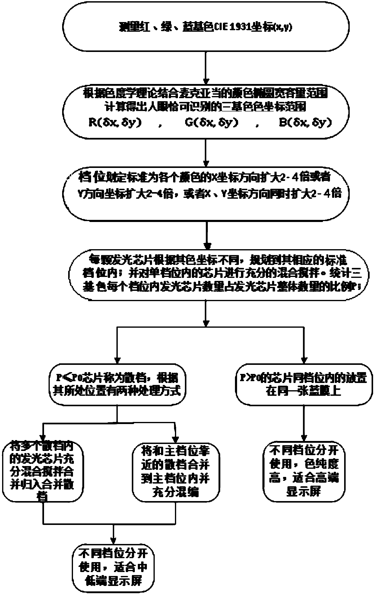
[0003] The technical problem to be solved by the present invention is to provide a light-emitting chi

Method used


Image

  • Light-emitting chip grading method based on mixed programming and color coordinate rough grading
  • Light-emitting chip grading method based on mixed programming and color coordinate rough grading
  • Light-emitting chip grading method based on mixed programming and color coordinate rough grading

Examples


Embodiment 1

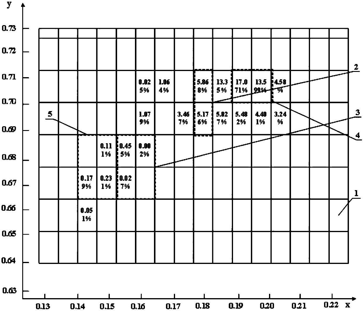
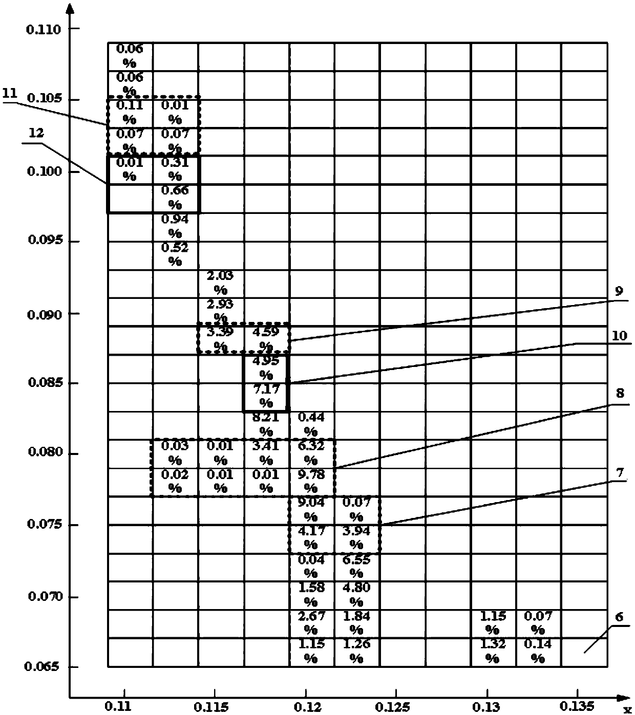
[0029] During the solid crystal operation, grab the light-emitting chips in the main file of each color standard and arrange them on a unit module. For example, during the solid crystal operation, red captures a light-emitting chip in a standard main file, and green captures figure 2 The light-emitting chip in the standard main file shown in the middle dotted line box 2, blue capture image 3 The light-emitting chip in the standard main file shown in the dotted line box 7. Modules with the same parameters are combined into one display screen. Although the color purity of the display screen produced in this way is slightly sacrificed, the light-emitting chips in the main files of each standard are fully mixed, there are no color blocks, and the number of gears is small, which is conducive to production management.

Embodiment 2

[0031] like figure 2 As shown, the scattered files represented by the dotted line box 3 and the scattered files represented by the dotted line box 5 are merged, and the light-emitting chips in the two scattered files are classified into one combined scattered file. During the solid crystal operation, red grabs a light-emitting chip in a standard main gear for use, and green grabs figure 2 The light-emitting chips in the merged file formed by the dotted line frame 3 and the dotted line frame 5 in the middle. blue grab image 3 The light-emitting chip in the standard main file shown in the thick solid line frame 10 in the middle. In this way, modules with the same parameters are combined into one display screen. Although the color purity of the display screen produced in this way is slightly sacrificed, it is fully mixed, has no color blocks, and has a small number of gears, which is conducive to production management.

Embodiment 3

[0033] like image 3 As shown, the dotted line box 11 and the thick solid line box 12 are combined into one combined scattered file. During the solid crystal operation, red grabs a light-emitting chip in a standard main gear for use, and green grabs figure 2 The light-emitting chip in the standard main file shown in the dotted line box 2. blue grab image 3 The dotted line box 11 and the thick solid line box 12 are combined into one combined light-emitting chip. In this way, modules with the same parameters are combined into one display screen. Although the color purity of the display screen produced in this way is slightly sacrificed, it is fully mixed, has no color blocks, and has a small number of gears, which is conducive to production management.


PUM


Abstract

The invention relates to a light-emitting chip grading method based on mixed programming and color coordinate rough grading. The color coordinate range of CIE 1931 which can be recognized by human eyes is expanded by 2-4 times in the X coordinate direction or expanded by 2-4 times in the Y coordinate direction, or is expanded by 2-4 times in both the X and Y coordinate directions, and the result is used as standard grading positions. The light-emitting chips in a grade are fully stirred and mixed, and a standard grade and a substandard grade are determined according to the proportion of the number of the LED light-emitting chips of the standard grade position in the overall number. The light-emitting chips of the same standard main grade are placed on the same one blue film for manufacturing a high-end small-spacing LED display screen. The light-emitting chips in the substandard grade are placed a blue film merging the substandard grades to manufacture a low-end display screen. Color consistency of the display screen can be guaranteed, the number of grading is small, engineering management is facilitated, and in-plant actual operation is facilitated. The method solves the problemsthat the number of the substandard grade positions which occupies a small portion is large, managing is difficult, and utilization is poor.

Description

technical field [0001] The invention belongs to the technical field of LED flat panel display, and in particular relates to a method for classifying light-emitting chips based on mixed coding and rough classification of color coordinates. Background technique [0002] At present, most of the light-emitting chips used in LED displays adopt the method of wavelength-brightness binning. The wavelength and brightness of the light-emitting chips in each gear are within a certain range, and the light-emitting chips in the same gear can be used in combination. However, there are different degrees of saturation differences in the cores of the same wavelength, and this difference is particularly obvious on small-pitch displays (dot pitch ≤ 2.0mm). Contents of the invention [0003] The technical problem to be solved by the present invention is to provide a light-emitting chip classification method based on mixed coding and rough classification of color coordinates. operate. [00...

Claims


Application Information

Patent Timeline
IPC IPC(8): B07C5/342
CPCB07C5/342
Inventor 郑喜凤王瑞光苗静陈宇丁铁夫
Owner CHANGCHUN CEDAR ELECTRONICS TECH CO LTD
Why Eureka
Try Eureka