
Light-emitting chip gear dividing method according to different color coordinate areas

A technology of light-emitting chips and color coordinates, which is applied in sorting and other directions, can solve the problems of poor color consistency of the display screen and small number of color coordinates, and achieve color consistency assurance, small number of bins, and cost savings. Effect

Inactive Publication Date: 2020-03-31
CHANGCHUN CEDAR ELECTRONICS TECH CO LTD
View PDF10 Cites 1 Cited by
  • Summary
  • Abstract
  • Description
  • Claims
  • Application Information

AI Technical Summary

Problems solved by technology

This method can not only solve the problem of poor color consistency of the display screen, but also has a small number of color coordinates, and there is no need for chip manufacturers to provide additional mixing operations, saving costs

Method used


Image

  • Light-emitting chip gear dividing method according to different color coordinate areas
  • Light-emitting chip gear dividing method according to different color coordinate areas

Examples


Embodiment 1

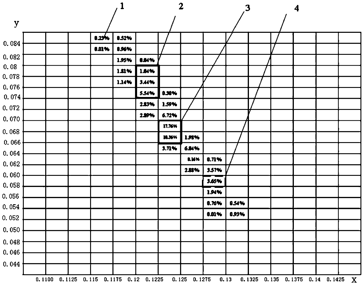
[0023] During the solid crystal operation, grab the light-emitting chips in a standard gear in the short-wavelength region of each color and arrange them on a unit module. For example, during the solid crystal operation, red grabs a light-emitting chip in a standard gear, green grabs a light-emitting chip in a standard gear, and blue grabs a light-emitting chip in a standard gear. figure 2 The short-wavelength region represented by grid 4 with the black dotted line in the middle uses the light-emitting chip in the gear. Modules with the same parameters are combined into one display screen. The display screen produced in this way has high color purity, no chromaticity problem, and good color consistency.

Embodiment 2

[0025] During the solid crystal operation, red grabs a light-emitting chip in a standard gear, green grabs a light-emitting chip in a standard gear, and blue grabs a light-emitting chip in a standard gear. figure 2 The long-wavelength region represented by the middle black solid line grid 2 uses the light-emitting chip in the gear. In this way, modules with the same parameters are combined into one display screen. Although the blue color of the display screen made in this way is a combination of the three standard gears, the human eye is not sensitive to the resolution of the blue long-wavelength region, so the display screen made in this way will not have chromaticity problems. And it effectively reduces the number of blue bins, which is convenient for production management and engineering operations.

Embodiment 3

[0027] During the solid crystal operation, red grabs a light-emitting chip in a standard gear, green grabs a light-emitting chip in a standard gear, and blue grabs a light-emitting chip in a standard gear. figure 2 The middle black solid line grid 3 represents the light-emitting chip in the middle wavelength region. In this way, modules with the same parameters are combined into one display screen. Although the blue color of the display screen made in this way is a combination of two standard gears, the human eye's ability to distinguish the mid-wavelength region of blue is moderate, so the display screen made in this way will not have chromaticity problems and is effective. The number of blue bins is reduced, which is convenient for production management and engineering operations.


PUM


Abstract

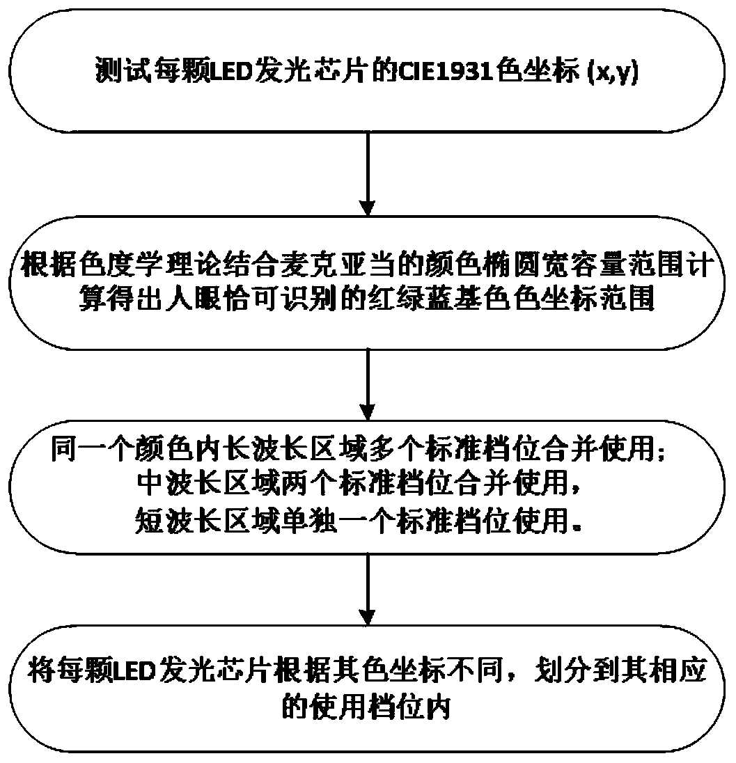
The invention relates to an light-emitting chip gear dividing method according to different color coordinate areas. The method comprises the following steps that a CIE 1931 color coordinate of an LEDlight-emitting chip is tested; a naked eye just noticeable CIE 1931 color coordinate range is determined as a standard gear according to the Maxadam color ellipse width capacity range of the chromaticity theory in combination with screen display effects; according to the naked eye just noticeable CIE 1931 color coordinate range, in the same color, 2-4 standard gears in a long wavelength area is combined into a using gear, 2 standard gears in a middle wavelength area is combined into a using gear, and 1 standard gear in a short wavelength area is used as a using gear; and the LED light emittingchip is divided into the corresponding using gears according different color coordinates of the chip. According to the method, color consistency of a display screen can be guaranteed, and the numberof gear dividing is small; and meanwhile, mixing treatment can be omitted by a chip manufacturer in each using gear, so that cost is saved.

Description

technical field [0001] The invention belongs to the technical field of LED flat panel displays, and in particular relates to a method for classifying light-emitting chips according to different color coordinate regions. Background technique [0002] At present, most of the light-emitting chips used in LED displays adopt the method of wavelength-brightness binning. The wavelength and brightness of the light-emitting chips in each gear are within a certain range, and the light-emitting chips in the same gear can be used in combination. However, there are different degrees of saturation differences in the cores of the same wavelength, and this difference is particularly obvious on small-pitch displays (dot pitch ≤ 2.0mm). Therefore, the LED display screen made by wavelength-brightness binning method will have different degrees of color difference, which will cause inconsistency in viewing by human eyes and affect the appearance of the display effect. Contents of the inventio...

Claims


Application Information

Patent Timeline
Patent Type & Authority Applications(China)
IPC IPC(8): B07C5/342
CPCB07C5/342
Inventor 苗静陆文文郭贵新程宏斌丁鉄夫
Owner CHANGCHUN CEDAR ELECTRONICS TECH CO LTD
Learn More