
Laser marking machine and laser processing system

A laser marking machine and laser technology, applied in the field of laser marking, can solve the problems of large space occupation, increased equipment weight in the power box, and easy loosening of wires, etc., to achieve convenient line connection, simplify equipment installation procedures, and reduce volume and the effect of weight

Pending Publication Date: 2019-03-29
SHENZHEN JPT OPTO ELECTRONICS CO LTD
View PDF0 Cites 0 Cited by
  • Summary
  • Abstract
  • Description
  • Claims
  • Application Information

AI Technical Summary

Problems solved by technology

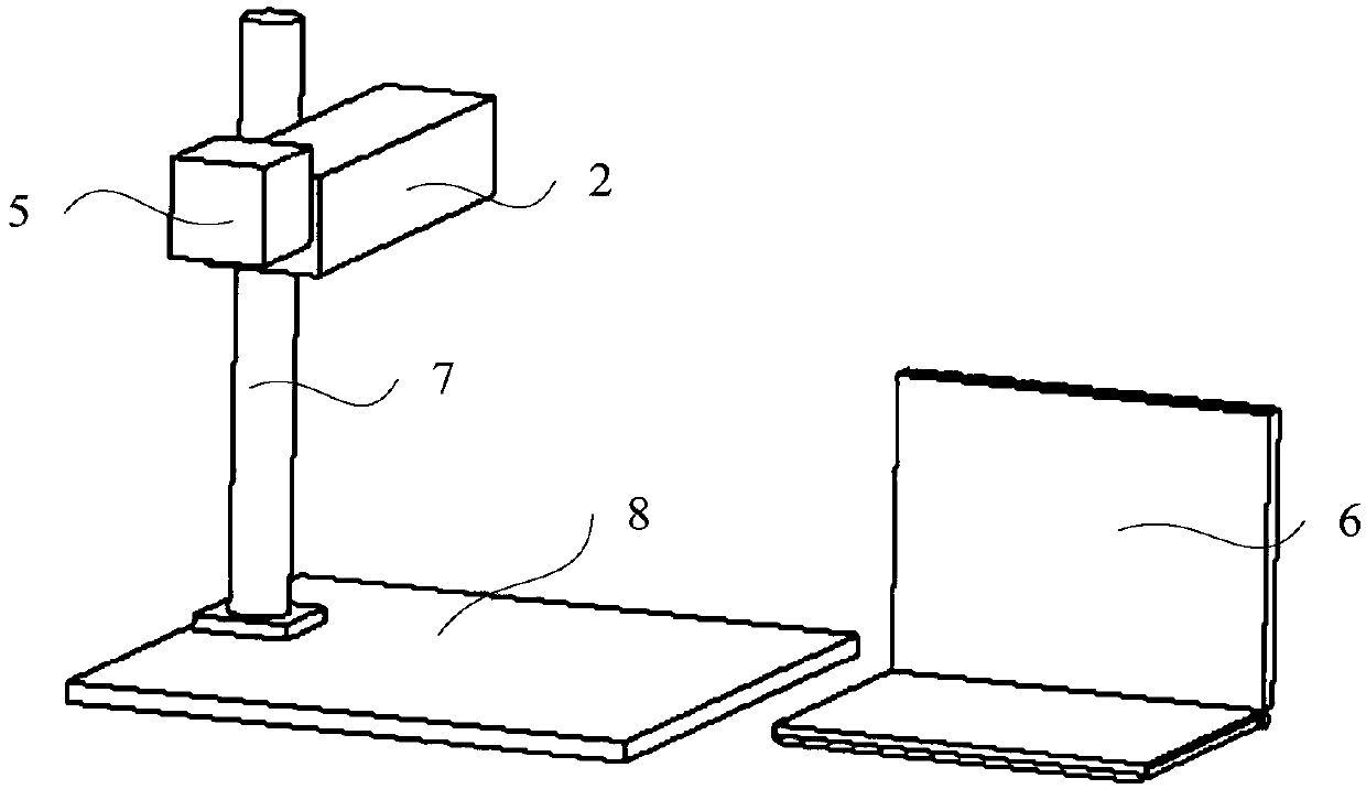
[0004] The purpose of this application is to provide a laser marking machine to solve the problem that the power box of the desktop laser marking machine in the prior art is set separately, resulting in that the wires are easy to loose when the power box is connected to the electrical components and the power box is equipped with additional equipment. Technical problems of weight and large space occupation

Method used


Image

  • Laser marking machine and laser processing system
  • Laser marking machine and laser processing system
  • Laser marking machine and laser processing system

Examples


Embodiment Construction

[0029] The technical solutions of the present invention will be clearly and completely described below in conjunction with the accompanying drawings. Apparently, the described embodiments are some of the embodiments of the present invention, but not all of them.

[0030] The components of the embodiments of the invention generally described and shown in the figures herein may be arranged and designed in a variety of different configurations. Accordingly, the following detailed description of the embodiments of the invention provided in the accompanying drawings is not intended to limit the scope of the claimed invention, but merely represents selected embodiments of the invention.

[0031] Based on the embodiments of the present invention, all other embodiments obtained by persons of ordinary skill in the art without making creative efforts belong to the protection scope of the present invention.

[0032] In the description of the present invention, it should be noted that the...


PUM


Abstract

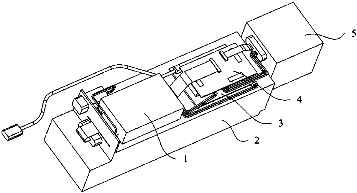
The invention relates to the technical field of laser marking, in particular to a laser marking machine and a laser processing system comprising the laser marking machine. The laser marking machine integrates a power supply group on a laser body, a laser marking card and a circuit conversion card are also arranged on the laser body, the power supply group respectively supplies power to the laser body and the circuit conversion card after converting voltage, and is connected with the laser marking card and a scanning galvanometer through the circuit conversion card, so that the laser marking card and the scanning galvanometer can achieve power supply and data transmission. And the laser marking card is connected with a computer through a USB cable, so that the marking function can be achieved. According to the invention, the power supply component is modularized and integrated on the laser body, so that a power supply box is omitted, and the overall size and weight of the device are greatly reduced; and after the power supply module is integrated on the laser body, the device arrangement simplicity is improved, the device installation process is simplified, and the connection stability of all components is improved.

Description

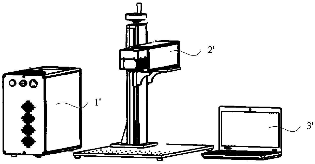
technical field [0001] The invention relates to the technical field of laser marking, in particular to a laser marking machine and a laser processing system including the laser marking machine. Background technique [0002] With the development of economy and the progress of society, laser marking is becoming more and more familiar to people. The laser marking machine is also more and more developed in the direction of light weight, portability, space saving, and easy maintenance. [0003] see figure 1 As shown, the structure of a common desktop laser marking machine generally includes a power box 1', a laser marking component 2' and a notebook computer 3' for controlling the laser marking component 2', and a laser power supply is embedded in the power box 1' , used to supply power to the laser marking component 2'. However, the existing power supply box 1' is installed separately. On the one hand, the power supply box 1' is connected to each electrical component by wires...

Claims


Application Information

Patent Timeline
IPC IPC(8): B23K26/362B23K26/70
CPCB23K26/362B23K26/702
Inventor 刘明曾海东
Owner SHENZHEN JPT OPTO ELECTRONICS CO LTD
Learn More