Machine room inspection system and working method thereof

A patrol inspection system and machine room technology, applied in manipulators, manufacturing tools, program-controlled manipulators, etc., can solve problems such as low work efficiency, inability to collect data without monitoring cameras, and inaccurate data collection, so as to reduce manual work intensity, Realize the effect of close-range shooting and accurate information collection

Active Publication Date: 2019-03-29
JD DIGITS HAIYI INFORMATION TECHNOLOGY CO LTD
View PDF11 Cites 41 Cited by
  • Summary
  • Abstract
  • Description
  • Claims
  • Application Information

AI Technical Summary

Problems solved by technology

This inspection method has high work intensity and low work efficiency. It requires the staff to hold the handle to continuously collect, and the collection speed is slow; and affected by the hand-held method and position, the data may be missed or the collection accuracy is poor.
[0004] The other is to collect device-related fault information through monitoring video, but because the video capture device is far away from the device, the collected data may be inaccurate, and the location without a monitoring camera cannot be collected, so a large number of monitoring cameras need to be installed
[0005] In addition, the above two inspection methods can only be used for inspection of the equipment in the computer room. For personnel activities in the computer room, the access management of the computer room needs to be operated by a dedicated person.

Method used


Image

  • Machine room inspection system and working method thereof
  • Machine room inspection system and working method thereof
  • Machine room inspection system and working method thereof

Examples


Embodiment Construction

[0069] The present invention will be described in detail below. In the following paragraphs, different aspects of the embodiments are defined in more detail. Aspects so defined may be combined with any other aspect or aspects unless specifically stated otherwise. In particular, any feature considered to be preferred or advantageous may be combined with one or more other features which are considered to be preferred or advantageous.

[0070] Terms such as "first" and "second" appearing in the present invention are only for convenience of description, to distinguish different components with the same name, and do not indicate a sequence or a primary and secondary relationship.

[0071] In the description of the present invention, orientations or positional relationships indicated by "upper", "lower", "top", "bottom", "front", "rear", "inner" and "outer" are used based on the attached The orientation or positional relationship shown in the figure is only for the convenience of ...


PUM


Abstract

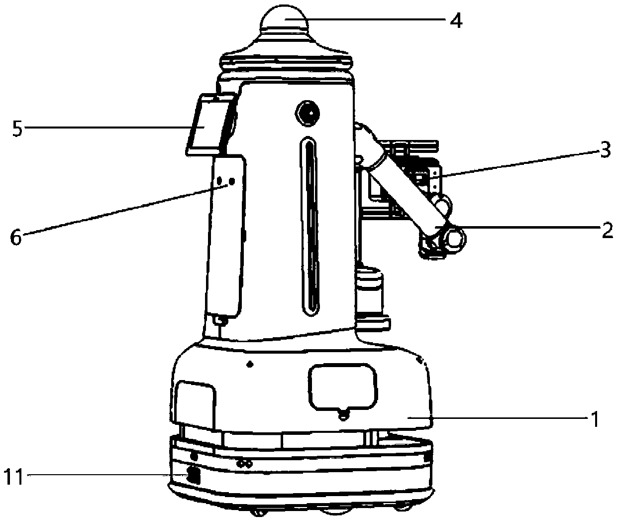
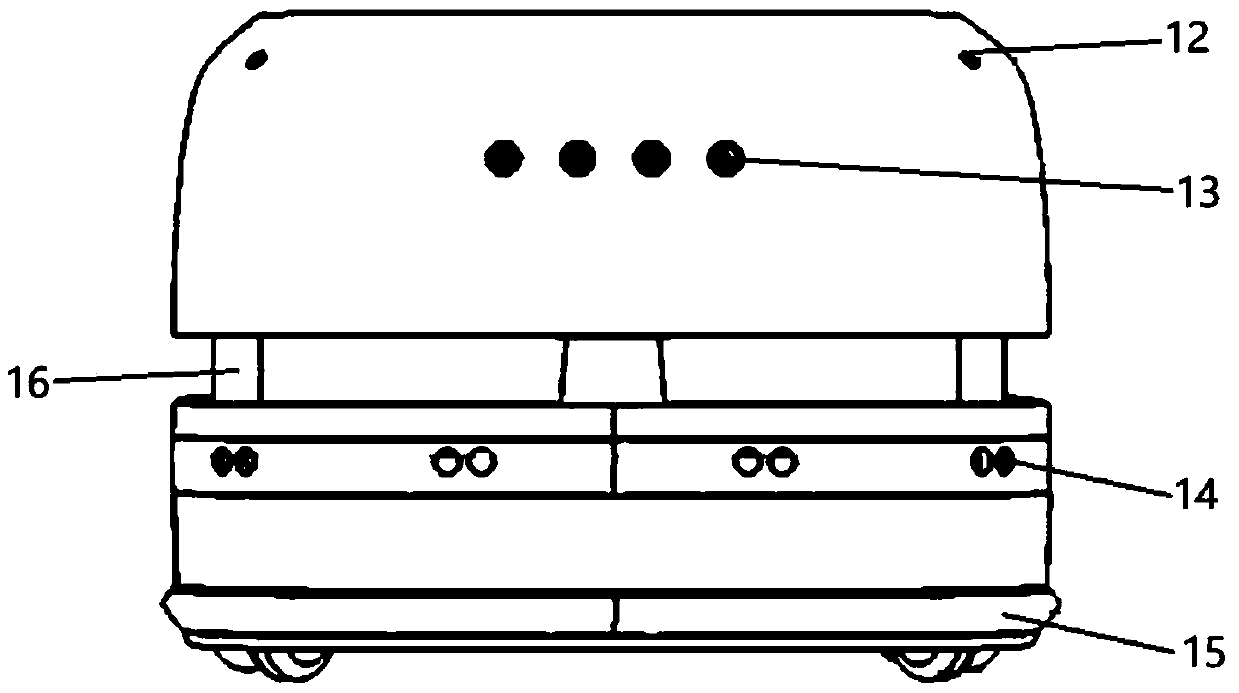
The invention relates to a machine room inspection system and a working method thereof. The inspection system comprises a movable robot and a mechanical arm, a movable robot, an information shooting part (31), a positioning detection part (32) and a control part, wherein the movable robot comprises a mechanical arm (2); the information shooting part (31) is arranged on the mechanical arm (2) terminal and is used for shooting the state attribute information of the equipment to be detected in the machine room; the positioning detection part (32) is arranged at the tail end of the mechanical arm(2) and is used for detecting the orientation information of the information shooting part (31) and the target to be shot; and the control part is used for moving the robot to the equipment to be detected according to the pre-planned route, according to the detection information provided by the positioning detection part (32), and the information shooting part is enabled to arrive at a proper shooting position for shooting by controlling the movement of the mechanical arm. According to the inspection system, equipment in the machine room can be intelligently inspected, and the inspection efficiency is improved; after the robot arrives at the equipment to be detected, the information shooting part is positioned to a proper shooting pose through the movement of the mechanical arm, so that the information acquisition is more accurate.

Description

technical field [0001] The invention relates to a machine room inspection system and a working method thereof. Background technique [0002] During the operation of the equipment in the computer room, equipment failures sometimes occur, which requires regular inspection of the equipment in the computer room. At present, two methods are mainly used for inspection. [0003] One is to rely on the staff to detect the related equipment in the computer room, collect the data through the hand-held detection equipment of the staff, and upload it to the server for data analysis. This inspection method has high work intensity and low work efficiency, and requires staff to hold the handle to continuously collect, and the collection speed is slow; and affected by the hand-held method and position, data may be missed or the collection accuracy is poor. [0004] The other is to collect equipment-related fault information through monitoring video, but because the video acquisition equipme...

Claims


Application Information

Patent Timeline
Patent Type & Authority Applications(China)
IPC IPC(8): B25J5/00B25J9/16B25J11/00B25J19/02
CPCB25J5/007B25J9/16B25J9/1676B25J11/00B25J19/02B25J19/023
Inventor 王重山姚秀军桂晨光秦宇邓超王超范涛银萍葛华鹏蔡禹丞
Owner JD DIGITS HAIYI INFORMATION TECHNOLOGY CO LTD
Why Eureka
Try Eureka