
Thin film perforating device

A punching device and film technology, applied in metal processing and other directions, can solve the problems of increasing processing difficulty, punching device cost, punch jamming, etc., and achieve low precision requirements of the contact surface, which is conducive to wide application and prevents The effect of freezing or shrinking

Pending Publication Date: 2019-03-29
深圳市龙华新区观澜凤鸣五金厂
View PDF0 Cites 0 Cited by
  • Summary
  • Abstract
  • Description
  • Claims
  • Application Information

AI Technical Summary

Problems solved by technology

[0003] The punch of the above-mentioned punching machine needs to be precisely matched with the sliding hole of the upper base and the punching hole of the lower die to punch out high-quality holes in the plastic film. Sometimes the matching gap between the two needs to be accurate to the μ level; however, this The high-precision punching machine is very susceptible to the influence of the external environment. For example, due to the influence of the ambient temperature, the thermal expansion and contraction of the parts will change the accuracy. The head is very easy to get stuck in the sliding hole of the upper base and the punching hole of the lower die, causing the punching machine to fail to operate. Frequent replacement of punches increases production costs; in addition, this high-precision fit also requires corresponding high-precision machining. However, due to the large contact area between the punch, the sliding hole and the punching hole, large-area processing The high-precision mating surface, on the one hand, increases the difficulty of processing, and on the other hand, the high processing cost makes the cost of the entire drilling device relatively high, which is not conducive to wide application

Method used


Image

  • Thin film perforating device
  • Thin film perforating device
  • Thin film perforating device

Examples


Embodiment Construction

[0020] In order to describe the technical content, structural features, and achieved effects of the present invention in detail, the following will be described in detail in conjunction with the embodiments and accompanying drawings.

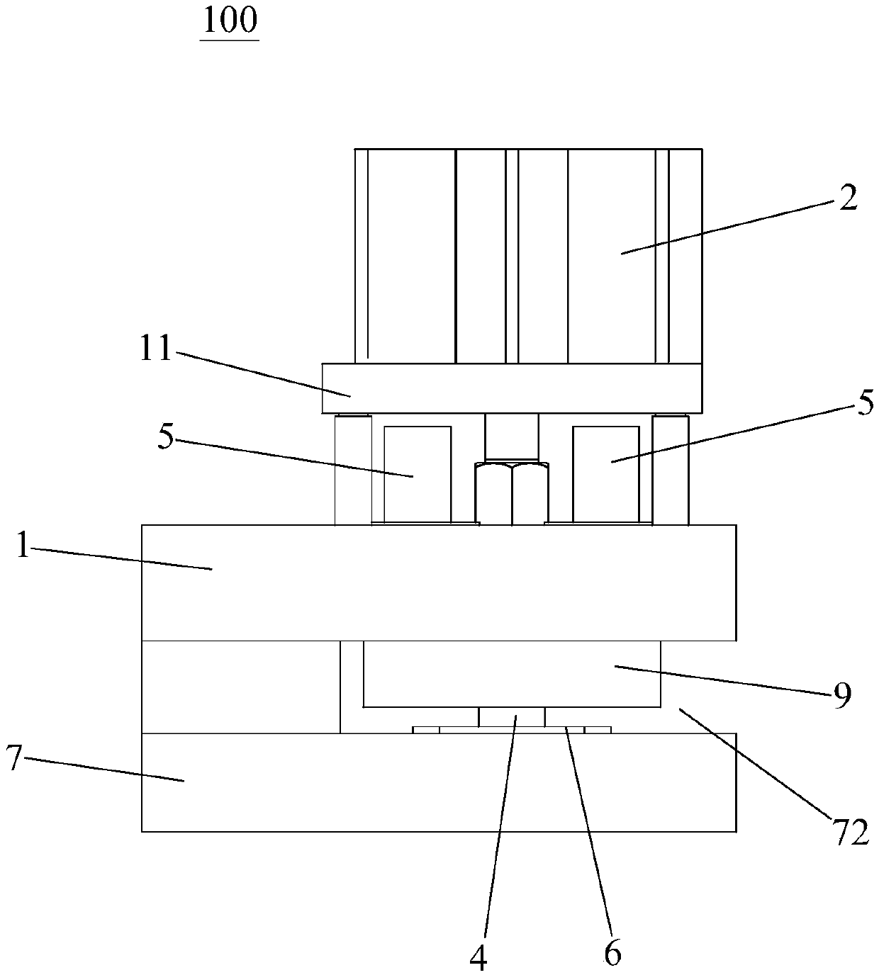
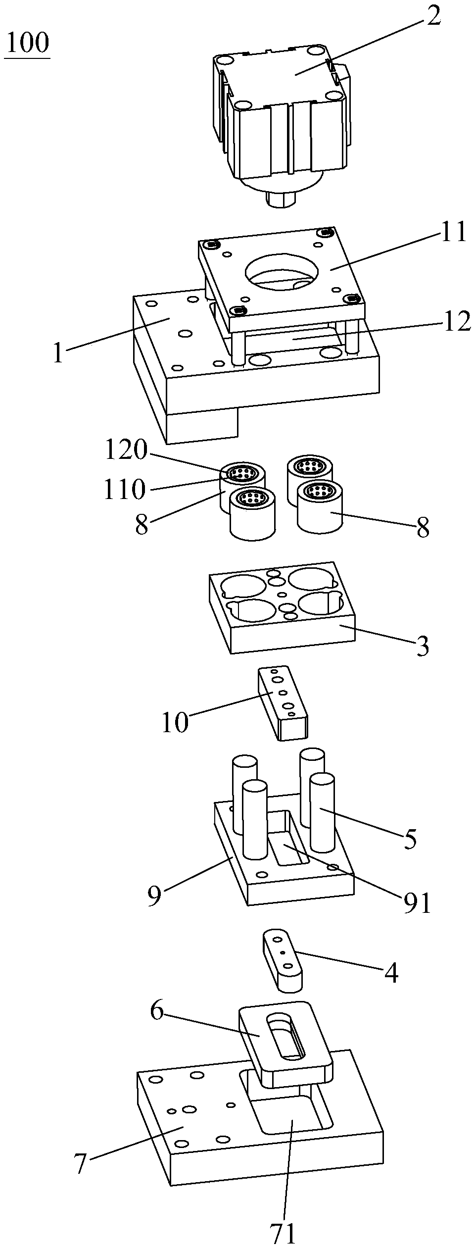
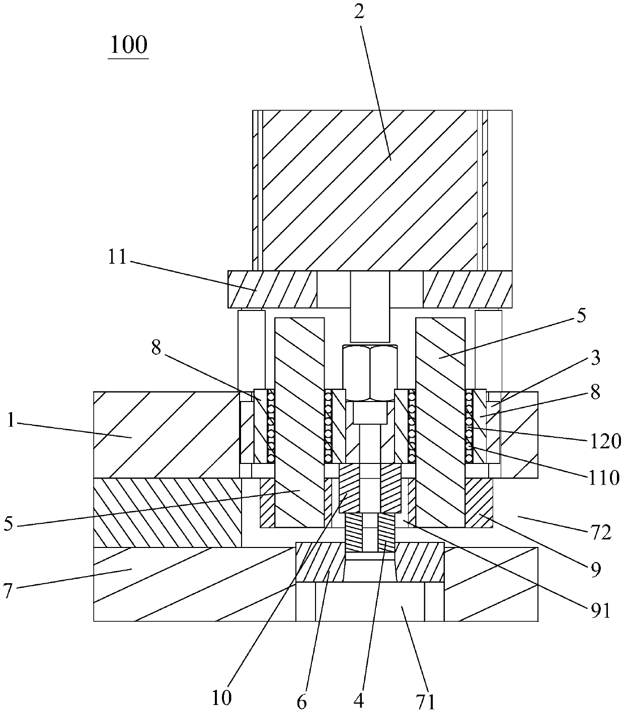
[0021] Such as figure 1 , figure 2 and image 3 As shown, the film punching device 100 of the present invention is suitable for the flexible packaging industry, and the film such as the handle of a plastic bag is perforated. The film punching device 100 of the first embodiment includes an upper base 1, a cylinder 2, a slider 3, a punching Head 4, guide column 5, lower mold 6 and lower base 7, a base frame 11 is arranged above the upper base 1, and the cylinder 2 is fixed on the base frame 11 of the upper base 1 and the output end It is downwardly connected with the slider 3, and the upper base 1 is provided with a sliding hole 12, and the slider 3 is slidably arranged in the sliding hole 12 and is in clearance fit with the sliding hole 12, so...


PUM


Abstract

The invention discloses a thin film perforating device. The thin film perforating device comprises an upper base, an air cylinder, a sliding block, a punch, guide columns and a lower die, wherein theair cylinder is fixed on the upper base, moreover, the output end of the air cylinder is connected with the sliding block in a downward direction, the upper base is provided with a sliding hole, the sliding block is arranged in the sliding hole in a sliding mode and is in clearance fit with the sliding hole, the punch is connected to the lower end of the sliding block, central shafts of the guidecolumns are arranged in the same direction as the output end of the air cylinder and are fixed to the upper base, guide sleeves are arranged on the sliding block, the guide sleeves sleeve the guide columns in a sliding mode, and the lower die is located below the punch. The thin film perforating device is not affected by environment temperature, high in precision, easy to machine and low in processing cost.

Description

technical field [0001] The invention relates to a film punching device, in particular to a film punching device which is not affected by ambient temperature, has high precision, is easy to process, and has low processing cost. Background technique [0002] In the processing of the flexible packaging industry, plastic bags are usually punched by a punching machine to punch holes in the plastic film during processing. The structure of the existing punching machine includes an upper base, a punch, a lower die and a cylinder, the upper base is provided with a sliding hole matched with the punch, the lower die is provided with a punching hole matched with the punch, and the plastic film or metal The sheet is set between the punch and the lower mold. When punching, the output end of the cylinder pushes the punch to slide down in the sliding hole of the upper base, so that the punch enters the sliding hole of the lower mold, so that the plastic film or A sheet of metal is punched ...

Claims


Application Information

Patent Timeline
Patent Type & Authority Applications(China)
IPC IPC(8): B26F1/02B26D7/00
CPCB26D7/0006B26F1/02
Inventor 向仲刚
Owner 深圳市龙华新区观澜凤鸣五金厂
Learn More