Wire discharging method, FDM printing device, storage medium and processor

A storage medium and wire unwinding technology, applied in the field of 3D printing, can solve problems such as abnormal wire unwinding, wire jamming, and different shapes

Active Publication Date: 2019-03-29
SHINING 3D TECH CO LTD
View PDF1 Cites 5 Cited by
  • Summary
  • Abstract
  • Description
  • Claims
  • Application Information

AI Technical Summary

Problems solved by technology

Since the material of the printing filament is softened when it is heated at a high temperature, it passes through a spring compression device ( figure 1 The point D shown in is the occlusal point of the printing wire), and the wire is flattened, so that the diameter of the wire becomes larger, which is larger than the diameter of the guide wire hole ( figure 1 The EF seg

Method used


Image

  • Wire discharging method, FDM printing device, storage medium and processor
  • Wire discharging method, FDM printing device, storage medium and processor

Examples


Embodiment 1

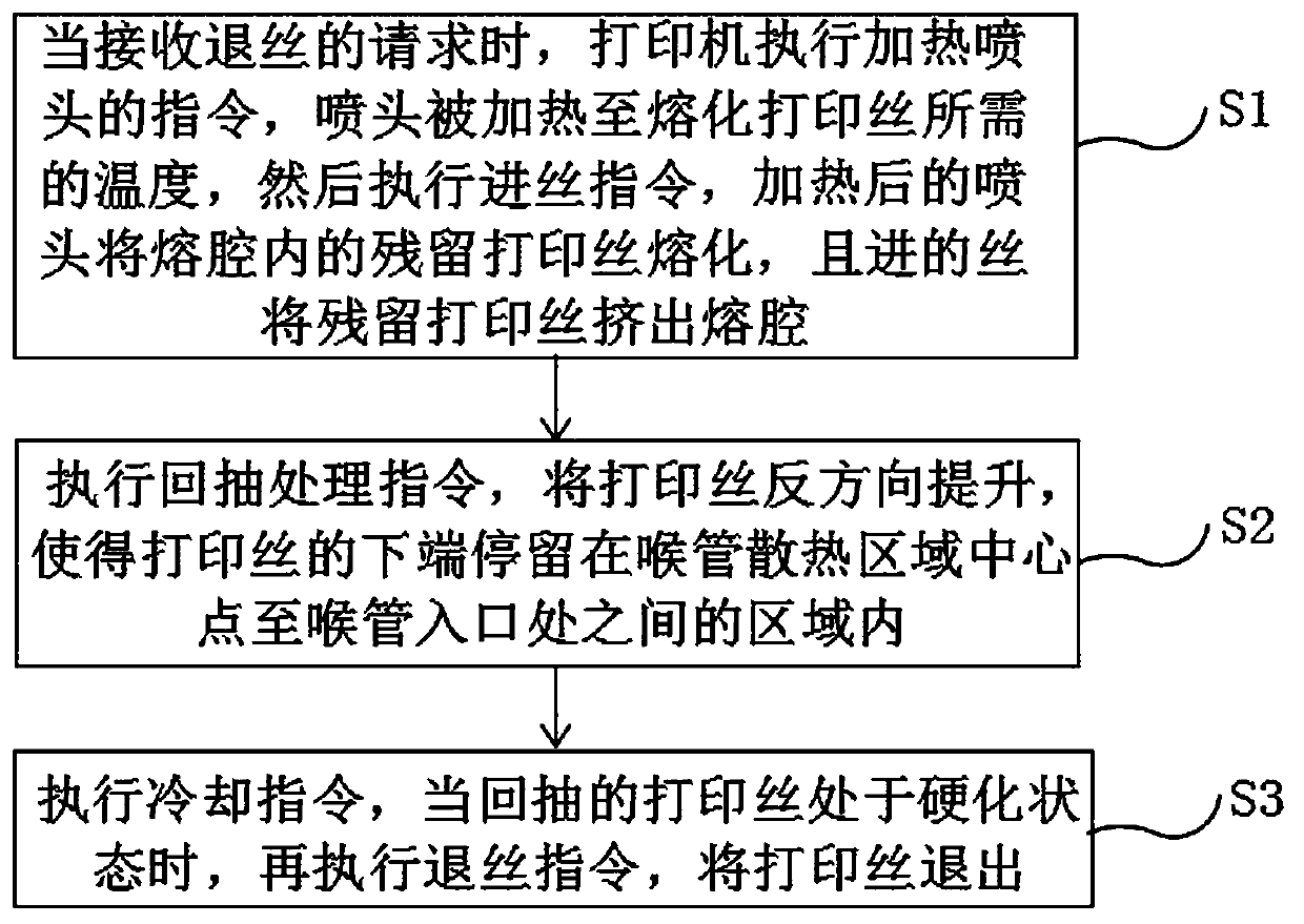
[0026] A kind of silk withdrawal method of the present invention, comprises steps as follows:

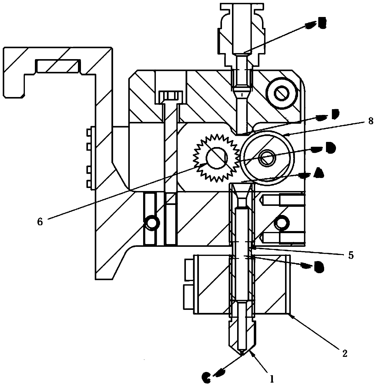
[0027] S1. When receiving the request to withdraw the filament, the printer executes the instruction of heating the nozzle, the nozzle is heated to the temperature required to melt the printing filament, and then executes the instruction of feeding the filament, assuming that this feeding is the first filament feeding, after heating The nozzle melts the residual printing filament in the BC segment of the melting cavity, and the first-passed filament squeezes the residual printing filament out of the BC segment of the melting cavity.

[0028] S1', the wire fed for the first time may be partially melted in the BC section of the melting cavity, so execute the wire feeding command again, and set this wire feeding as the second wire feeding, and the speed of the second wire feeding is faster than that of the first wire feeding The speed of the first wire feeding is to ensure that the sec...

Embodiment 2

[0038] A kind of FDM printing device, adopts the wire-removing method as described in embodiment 1.

[0039] As a preferred embodiment, the FDM printing device further includes a nozzle assembly, a heating assembly and a filament extrusion assembly.

Embodiment 3

[0041] A storage medium, the storage medium includes a stored program, wherein the wire unwinding method described in Embodiment 1 is executed when the program is running.

[0042] For the purposes of this specification, a "storage medium" may be any device that can contain, store, communicate, propagate or transmit programs for use in or in conjunction with instruction execution systems, devices or devices.

[0043]The storage medium described in this embodiment may be a computer-readable signal medium, a computer-readable storage medium, or any combination of the above two. More specific examples of storage media include at least (non-exhaustive list) the following: electrical connection with one or more wiring (electronic device), portable computer disk case (magnetic device), random access memory (RAM), read-only memory (ROM), erasable editable read-only memory (EPROM or flash memory), fiber optic devices, and portable read-only memory (CDROM).


PUM


Abstract

The invention discloses a wire discharging method, an FDM printing device, a storage medium and a processor. The wire discharging method comprises the steps that a printer carries out a command of heating a spray head when receiving a request of wire discharging, the spray head is heated to a temperature for melting printing wires, then a command of wire feeding is carried out, and the wire feeding is set as first wire feeding; residual printing wires in a melting cavity are melted by the heated spray head, and wires fed in the process of the first wire feeding squeeze the residual printing wires out of the melting cavity; a command of pullback treatment is carried out, the printing wires are lifted towards an opposite direction, and thus the lower ends of the printing wires are enabled tostay in an area between the center point of a heat dissipation area of a throat pipe and the entrance position of the throat pipe; and a cooling command is carried out, and when the printing wires after pullback are cooled to a hardened state, a wire discharging command is carried out to discharge the printing wires. According to the wire discharging method, the wires in the melting cavity are prevented from being brought out when the wire discharging is carried out, and the wires cannot be compressed flatly when passing a spring pressing device; the phenomenon of wire clamping is avoided, the wires in the melting cavity cannot be brought out, a wire guide hole is prevented from being hooked, and the success rate of wire discharging is guaranteed.

Description

technical field [0001] The invention relates to the technical field of 3D printing, and in particular to a wire unwinding method, an FDM printing device, a storage medium and a processor. Background technique [0002] FDM fused layer deposition modeling technology is a kind of 3D printing. It heats and melts filamentous hot-melt materials. At the same time, under the control of the computer, the three-dimensional nozzle selectively coats the material on the workbench according to the cross-sectional profile information. On, a layer of section is formed after rapid cooling. After one layer of molding is completed, the workbench is lowered to a height (that is, the thickness of the layer) and then the next layer is formed until the entire solid shape is formed. [0003] Since the feed of the FDM printer is driven by a pair of extrusion rollers, such as figure 1 As shown, the pair of extrusion-type rollers refers to the wire feeding driving wheel 6 and the wire feeding driven...

Claims


Application Information

Patent Timeline
IPC IPC(8): B29C64/118B29C64/357B33Y40/00
CPCB33Y40/00B29C64/118B29C64/357
Inventor 王海炳姚立伟陈磊陈帅
Owner SHINING 3D TECH CO LTD
Why Eureka
Try Eureka