
A rail vehicle traffic system

A technology for rail vehicles and transportation systems, applied in vehicle components, vehicle energy storage, railway vehicles, etc., can solve the problems of inaccessibility, waste of time, inconvenience, etc., and achieve the effect of saving time

Active Publication Date: 2020-12-22
CRRC QINGDAO SIFANG CO LTD
View PDF7 Cites 0 Cited by
  • Summary
  • Abstract
  • Description
  • Claims
  • Application Information

AI Technical Summary

Problems solved by technology

One of the main problems of rail vehicles is that people have to take rail vehicles at the station. At the same time, after people stop and get off at the station, they must go through the crowded station and choose to take different means of transportation to return home or go to their destination. This will cause people to waste a lot of time in taking transportation to go to the rail vehicles, and they must also go through the crowded crowds at the station to check tickets and enter the station
Moreover, most of the means of transportation that people choose after getting off the bus cannot enter narrow alleys or streets, so that people need to walk through narrow alleys or streets to reach their destinations after arriving at the station, causing a lot of inconvenience for people

Method used


Image

  • A rail vehicle traffic system
  • A rail vehicle traffic system
  • A rail vehicle traffic system

Examples


Embodiment 1

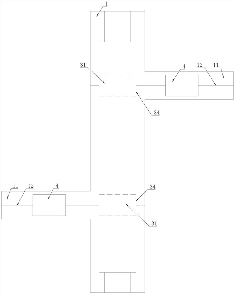
[0034] Such as Figure 1 to Figure 2 As shown, in the embodiment of the present invention, the rail vehicle 3 is provided with an accommodating cavity 21 for containing the movable vehicle 4, and the opposite sides of the accommodating cavity 21 parallel to the running direction of the rail vehicle 3 communicate with the outside world, and the movable vehicle 4 can pass through Two sides of the accommodation cavity 21 that communicate with the outside world enter and exit the accommodation cavity 21 . The lower side of the movable vehicle 4 is provided with a sliding device 45. After the movable vehicle 4 leaves the accommodating cavity 21, the sliding device 45 supports the movable vehicle 4 to move on the auxiliary track 11. The sliding device 45 is a pulley or other devices that can slide. The setting of the sliding device 45 on the mobile vehicle 4 has realized the purpose of the mobile vehicle 4 breaking away from the rail vehicle 3, the mobile vehicle 4 can not be restri...

Embodiment 2

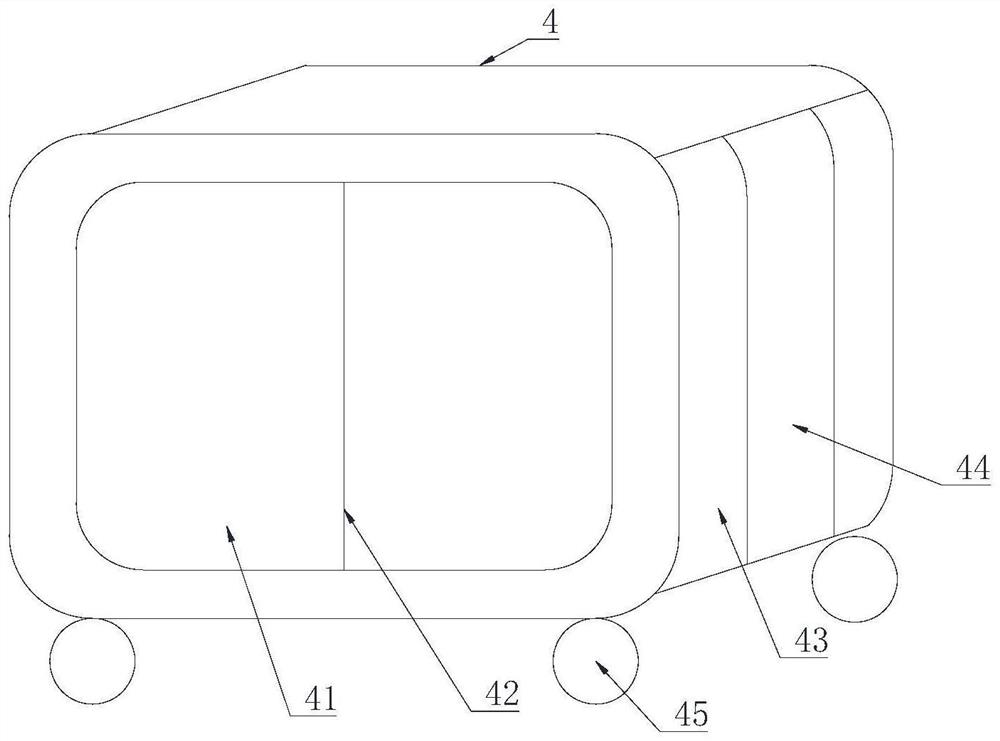
[0039] Such as image 3 As shown, in the embodiment of the present invention, the mobile vehicle 4 is provided with a first opening 41 communicating with the outside world on both sides perpendicular to its running direction, and the first opening 41 is provided with a first door covering the first opening 41 body 42 , the first door body 42 is opened, and passengers can enter and exit the mobile vehicle 4 through the first opening 41 . Preferably, the first door body 42 is set to be transparent, and passengers can see the outside world through the first door body 42 . The movable vehicle 4 is provided with a second opening 43 communicating with the outside world on opposite sides parallel to its running direction, and the second opening 43 is provided with a second door body 44 covering the second opening 43; The opposite sides on the running direction of the vehicle 3 are provided with a third opening 32 communicating with the interior of the rail vehicle 3. The third openi...

Embodiment 3

[0047] Such as Figure 4 As shown, in the embodiment of the present invention, a limiting device is arranged inside the housing chamber 21, and when the mobile vehicle 4 enters the housing chamber 21 from the housing chamber 21 through the side of the rail vehicle 3, the limiting device works to prevent the mobile vehicle 4 from entering the housing chamber 21. 21 slides out through the other side of the rail vehicle 3, and a locking structure is provided in the accommodation chamber 21. When the movable vehicle 4 enters the accommodation chamber 21 completely, the locking device works to lock the movable vehicle 4 in the accommodation chamber 21. The rail vehicle 3 stops, the fifth door body 37 is opened, the movable vehicle 4 enters the accommodation cavity 21 on the rail vehicle 3, and the limit device works to prevent the movable vehicle 4 from slipping out from the rail vehicle 3. After the accommodating chamber 21, the movable vehicle 4 stops moving, and the movable vehi...


PUM


Abstract

The invention discloses a rail car traffic system. The rail car traffic system comprises a rail and a rail car running along the rail. A movable car capable of being separated from the rail car to runis arranged on the rail car, and a containing cavity running through the rail car in the direction vertical to the running direction of the rail car is formed in the rail car. Auxiliary rails connected with the rail and vertical to the rail are arranged on the two sides, parallel to the running direction of the rail car, of the rail, and the movable car moves into or out of the containing cavityalong the auxiliary rails in order to run along with the rail car or be separated from the rail car. The containing cavity for containing the movable car is formed in the rail car, the movable car canenter the containing cavity to run along with the rail car and can also be separated from the rail car to independently run, and traffic jams are relieved through the small and flexible movable car.

Description

technical field [0001] The invention belongs to the field of rail vehicles, and in particular relates to a rail vehicle transportation system. Background technique [0002] At present, rail vehicles are the first choice for people to travel. Rail vehicles have large load capacity, fast speed and low price. With the advancement of technology and the increasing trend of population growth, rail vehicles are also facing huge challenges. To serve people better, we should follow the trend of the times and develop new technologies to better meet people's needs. One of the main problems of rail vehicles is that people have to take rail vehicles at the station. At the same time, after people stop and get off at the station, they must go through the crowded station and choose to take different means of transportation to return home or go to their destination. This will cause people to waste a lot of time going to rail vehicles by means of transportation, and they must also pass throu...

Claims


Application Information

Patent Timeline
Patent Type & Authority Patents(China)
IPC IPC(8): B61K1/00B60L53/14
CPCB60L2200/26B61K1/00Y02T10/70Y02T10/7072Y02T90/14
Inventor 张琪刘韶庆姜良奎庞世俊
Owner CRRC QINGDAO SIFANG CO LTD
Learn More