

Lifting adjustment device capable of adjusting freely and lifting method
A technology of adjusting device and lifting device, applied in the direction of lifting device, lifting frame, etc., can solve the problems that cannot be realized on site, the forklift movement requires a large space, and the installation accuracy is not high, and the effect of ensuring the front and rear moving distance is achieved.
- Summary
- Abstract
- Description
- Claims
- Application Information
AI Technical Summary
Problems solved by technology
Method used
Image

Examples
Embodiment 11
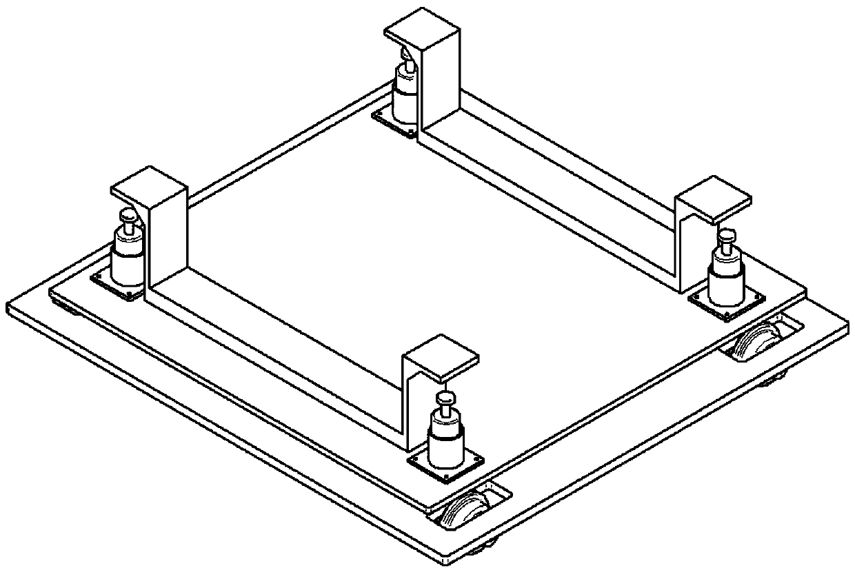
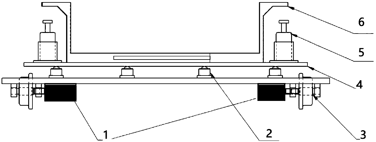
[0034] Embodiment 1.1: a lifting adjustment device, comprising a base plate, a wheel 1 is installed below the base plate, eight runners 2 are arranged above the base plate, an adjustment plate 4 is arranged above the runners 2, and a bracket 6 is connected above the adjustment plate 4. Lifting cylinders 5 are arranged on both sides of the bracket 6, and the installation accessories are placed on the bracket 6. The lifting adjustment device is lifted by the lifting cylinders 5 on both sides of the bracket 6; The runner 2 can ensure that the adjustment plate 4 can move freely on the plane of the base plate, and complete actions such as front and rear, left and right, and angular rotation; the bottom of the base plate is supported by the wheels 3, and the wheels 3 can walk on the railway track.
[0035] Be movably connected between support 6 and adjustment plate 4, so that when lift cylinder 5 rises or lowers, support 6 rises or lowers with lift cylinder 5.
[0036] The base of t...
Embodiment 12
[0041] Embodiment 1.2: A lifting adjustment device, the same as Embodiment 1.1, the difference is that a lifting cylinder II is also set between the adjustment plate and the bottom plate, and four right-angle stop structures are arranged above the bottom plate, which is convenient for positioning the adjustment plate and finding references Location.
[0042]The working method of embodiment 1.2 is: put the accessories on the lifting adjustment device described in this embodiment, move the lifting adjustment device to the position to be installed at the bottom of the frame, start the lifting cylinder II to make it rise , after the height of the adjustment plate 2' exceeds the height of the four right-angle stops, rotate the adjustment plate to the required angle, so that the accessories to be installed are adjusted to the position closest to the installation, and then start the lifting cylinder 3', so as to pass through the lifting cylinder The platform support of 3' and bracket...
Embodiment 13
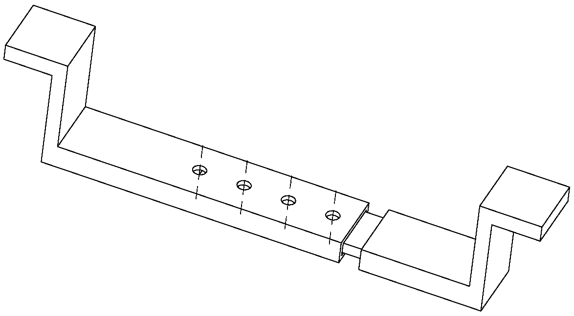
[0043] Embodiment 1.3: a kind of lifting adjustment device, with embodiment 1.2, the difference is: as image 3 As shown, the bracket 6" is a telescopic structure, the left part of the bracket 6" is fixed on the adjustment plate 4, and the right part of the bracket 6" includes a slide bar, which passes through the opening of the adjustment plate 4" and is connected to the bracket 6". The bottom of the right part, so that the right part of the bracket 6" can slide left and right along the opening of the adjustment plate 4", the width of the opening of the adjustment plate 4" is smaller than the width of the slide bar, and the width of the opening of the adjustment plate 4" is also smaller than The width of the bracket is 6", so as to adapt to the installation of accessories of different sizes and different positions.
[0044] In this embodiment, the lifting cylinder 5" is also fixedly connected to the slide bar through the opening of the adjustment plate 4", so that when the sl...
PUM
 Abstract
Description
Claims
Application Information