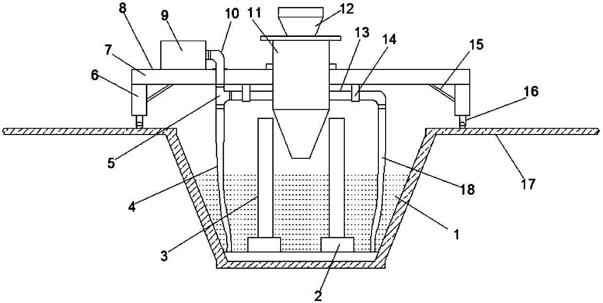
Civil engineering building backfilling device

A technology for civil air defense engineering and construction, applied in construction, earthmoving machines/shovels, etc., can solve problems such as increasing leakage plugging procedures and costs, improving labor intensity, affecting construction period, etc., and improving the quality and efficiency of backfill soil. , The effect of reducing the cost of plugging and avoiding failure

Pending Publication Date: 2019-03-29
安徽省人防建筑设计研究院
View PDF8 Cites 4 Cited by
  • Summary
  • Abstract
  • Description
  • Claims
  • Application Information

AI Technical Summary

Problems solved by technology

[0002] Civil air defense engineering refers to the underground protective building built separately to protect personnel and materials, and the basement built in combination with ground buildings that can be used for air defense. According to the purpose, it can be divided into command and communication, personnel shelter, medical use, ambulance station, and warehouse. As well as garages, etc. At present, in the process of earthwork backfilling in the basement, some backfilling areas will be encountered, the area of ​​which is small, especially the distance between the frame columns in this area is small, the earthwork machinery cannot pass between the frame columns, and the foundation pit is due to There will be accumulated water in the rain, and the accumulated water cannot be discharged, and it will be dried naturally, which will affect the construction period
In addition, when backfilling narrow and deep foundation pits, only the method of backfilling with soil can be adopted. During the process of soil dumping, it will inevitably impact the waterproof protective layer of the underground main structure, resulting in damage to the waterproof protective layer and coiled materials, which increases the risk of later plugging. The process and cost of the operation; at the same time, throwing soil backfill increases labor intensity and reduces backfill efficiency and quality

Method used


Image

  • Civil engineering building backfilling device

Examples


Embodiment Construction

[0017] The following will clearly and completely describe the technical solutions in the embodiments of the present invention with reference to the accompanying drawings in the embodiments of the present invention. Obviously, the described embodiments are only some, not all, embodiments of the present invention.

[0018] In describing the present invention, it should be understood that the terms "upper", "lower", "front", "rear", "left", "right", "top", "bottom", "inner", " The orientation or positional relationship indicated by "outside", etc. is based on the orientation or positional relationship shown in the drawings, and is only for the convenience of describing the present invention and simplifying the description, rather than indicating or implying that the referred device or element must have a specific orientation, so as to Specific orientation configurations and operations, therefore, are not to be construed as limitations on the invention.

[0019] According to an em...


PUM


Abstract

The invention discloses a civil engineering building backfilling device. The device comprises a foundation pit; a pair of bearing platforms are arranged at the bottom of the foundation pit, a frame column is arranged at the top end of each bearing platform in the height direction of the bearing platform, and a guide tool of the backfilling device is arranged above the foundation pit; and the guidetool comprises a horizontal frame, a funnel cavity and rolling wheels, wherein the funnel cavity is arranged at the center of the horizontal frame. The device has the beneficial effects that due to the arrangement of the guide tool, the defect of traditional soil throwing to backfill is overcome, the failure of a waterproof protection layer caused by earthwork impact is avoided, the quality and the efficiency of the backfilling soil are improved, the reworking is reduced, and the later plugging cost is reduced; in addition, water pumping pipes and a water pump are combined, the problem of water accumulation in the foundation pit area is solved, and meanwhile, the problem that due to the fact that the area of the backfilling area is narrow, a backfilling machine is inconvenient to pass through is solved; and the engineering is enabled to be carried out in a non-turbulent mode, the construction period is not affected, and the practicability is high.

Description

technical field [0001] The invention relates to the technical field of civil air defense engineering, in particular to a backfill device for civil air defense engineering buildings. Background technique [0002] Civil air defense engineering refers to the underground protective building built separately to protect personnel and materials, and the basement that can be used for air defense built in combination with ground buildings. As well as garages, etc. At present, in the process of earthwork backfilling in the basement, some backfilling areas will be encountered, the area of ​​which is small, especially the distance between the frame columns in this area is small, the earthwork machinery cannot pass between the frame columns, and the foundation pit is due to There will be accumulated water in the rain, which cannot be discharged, and it will be dried naturally, which will affect the construction period. In addition, when backfilling narrow and deep foundation pits, only ...

Claims


Application Information

Patent Timeline
Patent Type & Authority Applications(China)
IPC IPC(8): E02F5/22
CPCE02F5/223
Inventor 甘伟
Owner 安徽省人防建筑设计研究院
Why Eureka
Try Eureka