Concrete pumping device

A pumping device and concrete technology, which is applied in construction, building structure, construction material processing and other directions, can solve the problems of insufficient stability of pumping device, easy spillage of materials, easy blockage of conveying hopper, etc. Smooth, full use of materials, good circulation effect

Inactive Publication Date: 2019-03-29
FOSHAN UNIVERSITY
View PDF3 Cites 2 Cited by
  • Summary
  • Abstract
  • Description
  • Claims
  • Application Information

AI Technical Summary

Problems solved by technology

[0004] The purpose of the present invention is to provide a concrete pumping device, by arranging a stirring assembly inside the delivery hopper and a filter cartridge on the delivery pipeline to avoid clogging, setting baffles on the delivery hopper and the upper hopper to prevent material from spilling, Four brackets are used to improve the stability of the pumping device, which solves the problems that the existing conveying hopper is easy to block, the material is easy to spill during the conveying process, and the stability of the pumping device is not high enough when it is working.

Method used


Image

  • Concrete pumping device
  • Concrete pumping device
  • Concrete pumping device

Examples


Embodiment Construction

[0038] The following will clearly and completely describe the technical solutions in the embodiments of the present invention with reference to the accompanying drawings in the embodiments of the present invention. Obviously, the described embodiments are only some, not all, embodiments of the present invention. Based on the embodiments of the present invention, all other embodiments obtained by persons of ordinary skill in the art without creative efforts fall within the protection scope of the present invention.

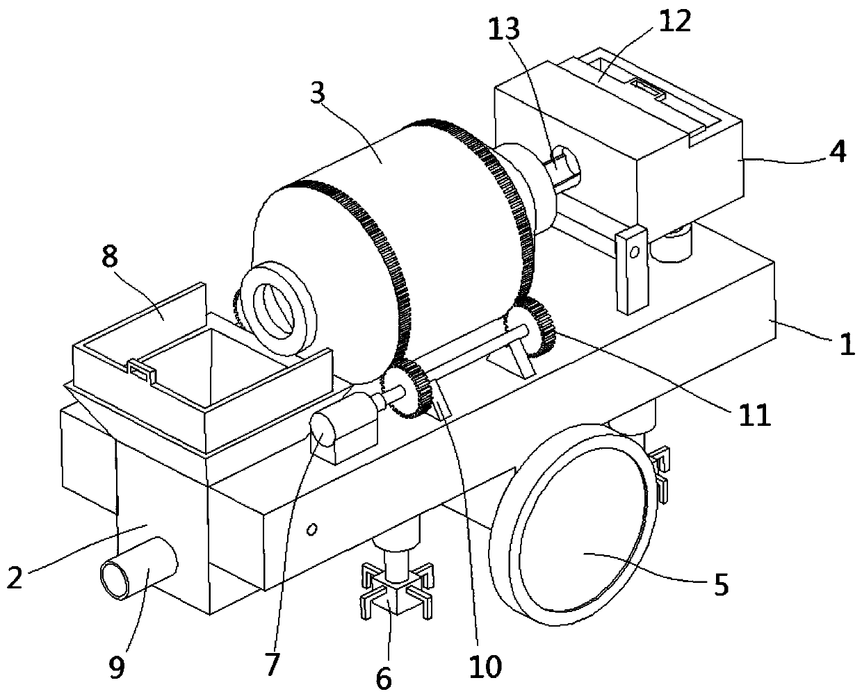
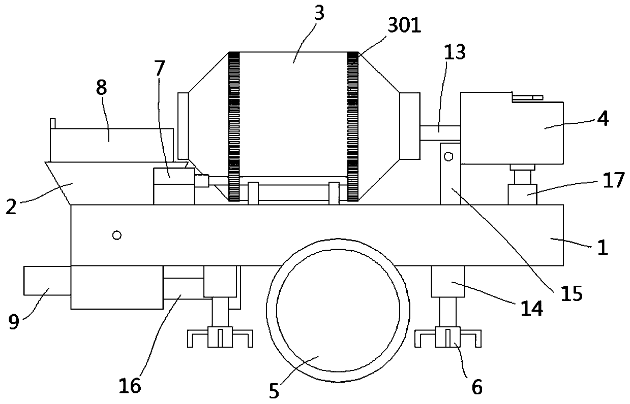
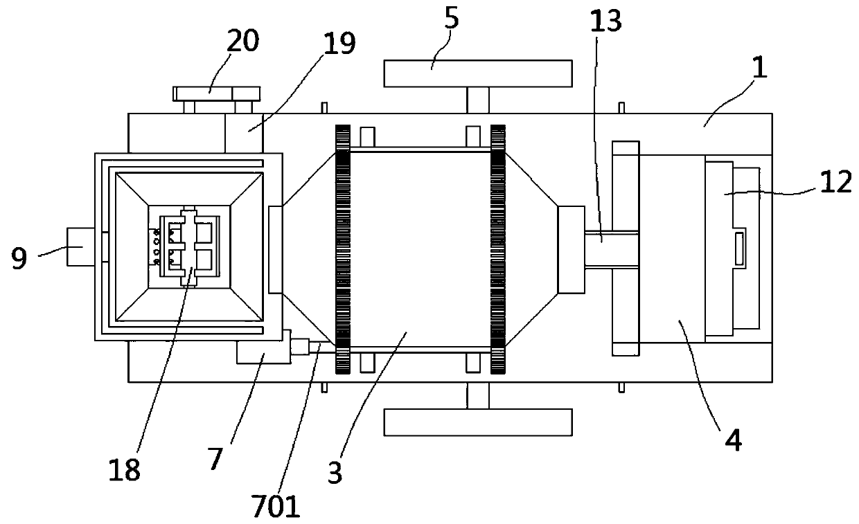
[0039] see Figure 1-12 As shown, the present invention is a concrete pumping device, comprising a base 1, a conveying hopper 2, a mixing drum 3 and an upper hopper 4, and two wheels 5 are rotatably connected to one surface of the base 1; a groove 101 is formed on a surface of the base 1; The inner wall of the groove 101 is fixedly connected with one surface of the conveying hopper 2; four first hydraulic rods 14 are fixed on one surface of the base 1; the other en...


PUM


Abstract

The invention discloses a concrete pumping device and relates to the technical field of pumping equipment. The device comprises a base, a conveying hopper, a stirring roller and a feeding hopper, andmultiple wheels are rotatably connected to one surface of the base; a groove is formed in one surface of the base; the inner wall of the groove is fixedly connected with one surface of the conveying hopper; multiple first hydraulic rods are fixed to one surface of the base; a supporting block is fixed to the other end of each first hydraulic rod; multiple second hydraulic rods are fixed to one surface of the base; a T-shaped slide block is fixed to the other end of each second hydraulic rod; one surface of each T-shaped slide block is slidingly connected with one surface of the feeding hopper;a first motor is fixed to one surface of the base. According to the concrete pumping device, a stirring assembly is arranged in the conveying hopper, a filter cylinder is arranged on a conveying pipe, blocking is avoided, baffles are arranged on the conveying hopper and the feeding hopper, so that materials are prevented from being scattered, four supports are arranged on the supporting blocks, so that the stability of the pumping device is improved, and the concrete pumping device has the advantage of stable working.

Description

technical field [0001] The invention belongs to the technical field of pumping equipment, in particular to a concrete pumping device. Background technique [0002] Concrete is concrete, and the concrete pumping machine is a machine that uses pressure to continuously transport concrete along the pipeline. It consists of pump body and delivery pipe. According to the structural form, it is divided into piston type, extrusion type and hydraulic diaphragm type. The pump body is installed on the chassis of the car, and then equipped with a telescopic or inflection boom, a pump truck is formed. [0003] When the existing concrete pumping device feeds the mixed concrete into the conveying hopper through the mixing drum, if the material size is large, it is easy to cause blockage inside the conveying pipeline, and at the same time, when the concrete flow is large and piled up inside the conveying hopper, it is easy to make the inside of the conveying hopper blockage; and when the ...

Claims


Application Information

Patent Timeline
Patent Type & Authority Applications(China)
IPC IPC(8): E04G21/04
CPCE04G21/04
Inventor 雷元新徐佳兴邓坚黄雅攀
Owner FOSHAN UNIVERSITY
Why Eureka
Try Eureka