Hydro-driving radial vibration well cementing short segment and using method thereof

A technology of radial vibration and hydraulic drive, which is applied in the direction of vibration generating devices, earthwork drilling and production, wellbore/well components, etc., and can solve wellbore unsafe accidents, soft formation medium falling or collapsing, and pipe strings that are easy to touch wells to improve cementing quality, wide effective vibration range, and improve displacement efficiency

Pending Publication Date: 2019-03-29
BC P INC CHINA NAT PETROLEUM CORP +1
View PDF0 Cites 0 Cited by
  • Summary
  • Abstract
  • Description
  • Claims
  • Application Information

AI Technical Summary

Problems solved by technology

The hydraulic pulse vibration cementing tool in the prior art is a hydraulically driven eccentric turbine, and the eccentric turbine makes periodic circular motions along the axial direction, thereby driving the circular vibration of the entire casing string, but there are still defects: the circular vibration of the pipe string is easy to touch Hit the well wall, causing the soft medium in the formation to fall or collapse, thereby blocking the annulus and causing unsafe wellbore accidents

Method used


Image

  • Hydro-driving radial vibration well cementing short segment and using method thereof
  • Hydro-driving radial vibration well cementing short segment and using method thereof
  • Hydro-driving radial vibration well cementing short segment and using method thereof

Examples


Embodiment 1

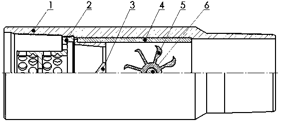
[0030] A hydraulically driven radial vibration cementing pup joint at least includes a body 1, which is characterized in that: the body 1 is a tubular cylinder with two ends open, and the two ends are provided with threads connected with matching casing strings. The body 1 A filter device is fixed inside the opening at one end, and a limit mechanism is fixed on the inner wall of the end of the body 1 far away from the filter device. A plurality of vibration units connected end to end are arranged in the body 1 between the filter device and the limit mechanism. The diameter matches the diameter of the body 1; the axis of the filter device, the vibration unit and the axis of the body 1 coincide, and the inner diameter of the filter device and the vibration unit form a flow passage.

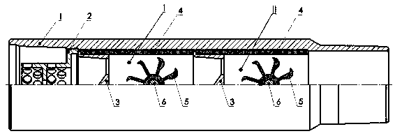
[0031] When the present invention is used, due to the design of multiple vibration units, such as Figure 1-2 The shown includes two vibration units, which can produce superimposed vibration effects dur...

Embodiment 2

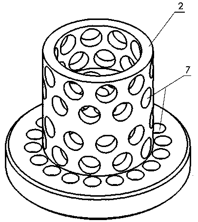
[0034] Such as Picture 1-1 , Figure 1-2 , figure 2 As shown, it is an improvement on the basis of embodiment 1. The filter device is threadedly connected to the opening at one end of the body 1. The filter device is a filter basket 2. The side wall of the filter basket 2 is provided with several filters along its radial direction. Hole 7.

[0035] The filter basket 2 is a cylindrical structure with two ends open, wherein the filter basket 2 is provided with a convex edge at one end close to the vibration unit, and the convex edge is provided with an external thread fixedly connected with the internal thread of the end of the body 1; A number of filter holes 7 are also opened in the length direction, and a number of filter holes 7 on the convex edge are arranged along the circumferential direction.

[0036] When in use, the filter basket 2 is made of aluminum alloy material. The filter basket 2 has high strength, good statues, excellent thermal conductivity, and good corrosion res...

Embodiment 3

[0038] Such as Picture 1-1 , Figure 1-2 ,, Figure 4 As shown, it is an improvement on the basis of embodiment 1 and embodiment 2. The vibration unit includes a support sleeve 4 and a deflector tube 3 located inside the support sleeve 4, a polarized waterwheel ball wheel 5 and a bearing 6. The support sleeve 4 and the guide tube 3 are both cylindrical structures with open ends. The guide tube 3 is fixed on the side of the support sleeve 4 close to the filter device, and the side wall of the support sleeve 4 away from the filter device runs along the radial direction. A set of through holes 9 for mounting the bearing 6 is opened, the bearing 6 is vertically fixed inside the support sleeve 4 through the through hole 9, and the polarized waterwheel ball wheel 5 is fixed on the rotating shaft of the bearing 6.

[0039] When in use, the liquid that has been filtered out of impurities by the filter basket 2 then enters the vibration unit. First, it passes through the guide tube 3, and ...


PUM


Abstract

The invention discloses a hydro-driving radial vibration well cementing short segment and a using method thereof. The short segment at least comprises a body, the body is a tubular column body which openings formed in the two ends and threads arranged at the two ends, a filtering device is fixed to the opening of one end of the body, a limiting mechanism is arranged on the inner wall of the end, away from the filtering device, of the body, multiple vibration units which are sequentially connected end to end are arranged between the filtering device and the limiting mechanism, and the diametersof the vibration units are matched with the diameter of the body; the axes of the filtering device, the vibration units and the body overlap, and a flow passage is formed by the inner diameters of the filtering device and the vibration units. The vibration manner of the multiple groups of the vibration units is longitudinal regular movement, overlaying vibration effect can be generated in on-siteoperation, so that strong vibration is transmitted further, the effective vibration range of a sleeve tube string is wider, mud cakes on a sleeve tube column and a well wall is effectively flushed, the rheological property of drilling fluid is improved, the flowing of the drilling fluid is easier, and the displacement efficiency is improved to facilitate the gluing of a cement ring and the sleevetube column and the well wall.

Description

Technical field [0001] The invention belongs to the technical field of oil field development, and in particular relates to a hydraulically driven radial vibration cementing sub for cementing operations and a use method. Background technique [0002] Cementing is an important part of well construction in oil and gas fields. Cementing quality has an important influence on maintaining the stability of the wellbore and the stable production of oil and gas fields. Cementing works are affected by many factors, which increase the difficulty of construction. During cementing, after the oil and gas wells are injected with cement, due to factors such as formation pressure imbalance, fluids in the formation flow into the annulus of the oil and gas wells, resulting in annulus channeling, of which gas channeling is most likely to occur. [0003] In the process of cementing, vibrating cement slurry is one of the effective technical means to improve cementing quality. Vibration cementing techno...

Claims


Application Information

Patent Timeline
Patent Type & Authority Applications(China)
IPC IPC(8): E21B33/13E21B28/00
CPCE21B28/00E21B33/13
Inventor 陈鹏伟许朝阳李慧升
Owner BC P INC CHINA NAT PETROLEUM CORP
Why Eureka
Try Eureka