Multifunctional friction wear testing device

A friction and wear test, multi-functional technology, used in measuring devices, testing wear resistance, instruments, etc., can solve the problems of waste of equipment resources, increased experimental costs, complex working conditions, etc., to facilitate the overall installation and replacement and disassembly, reduce The overall cost of the equipment, the effect of easy installation and disassembly

Active Publication Date: 2019-03-29
HOHAI UNIV CHANGZHOU
View PDF10 Cites 11 Cited by
  • Summary
  • Abstract
  • Description
  • Claims
  • Application Information

AI Technical Summary

Problems solved by technology

Different friction and wear testing machines have been manufactured on the market for these friction and wear forms, such as MHK-500 ring block friction and wear testing machine, WMJ-1500 reciprocating friction testing machine, etc., but in the actual test process, we will encounter more than one In order to meet the requirements of the test, we usually purchase multiple friction and wear testing machines with different motion forms, which results in a substantial increase in the cost of the experiment and a waste of equipment resources
Of course, the UMT series multifunctional friction and wear testing machine of the US CETR company can perform tribological tests of various friction pairs, but the price is expensive.
[0004] In addition, the friction and wear testing machines on the market have a very high degree of integration, so when designing the external load of the simulated working condition, it is often simply to use the rated force loading method
However, the actual working conditions are more complicated, and the combination of different speeds and different external loads has a very different impact on the friction and wear test.
In addition, the existing friction testing machine is also suitable for a variety of samples of different shapes and sizes, and it is inconvenient to adjust the axes and centers of the upper and lower samples.

Method used


Image

  • Multifunctional friction wear testing device
  • Multifunctional friction wear testing device
  • Multifunctional friction wear testing device

Examples


Embodiment 1

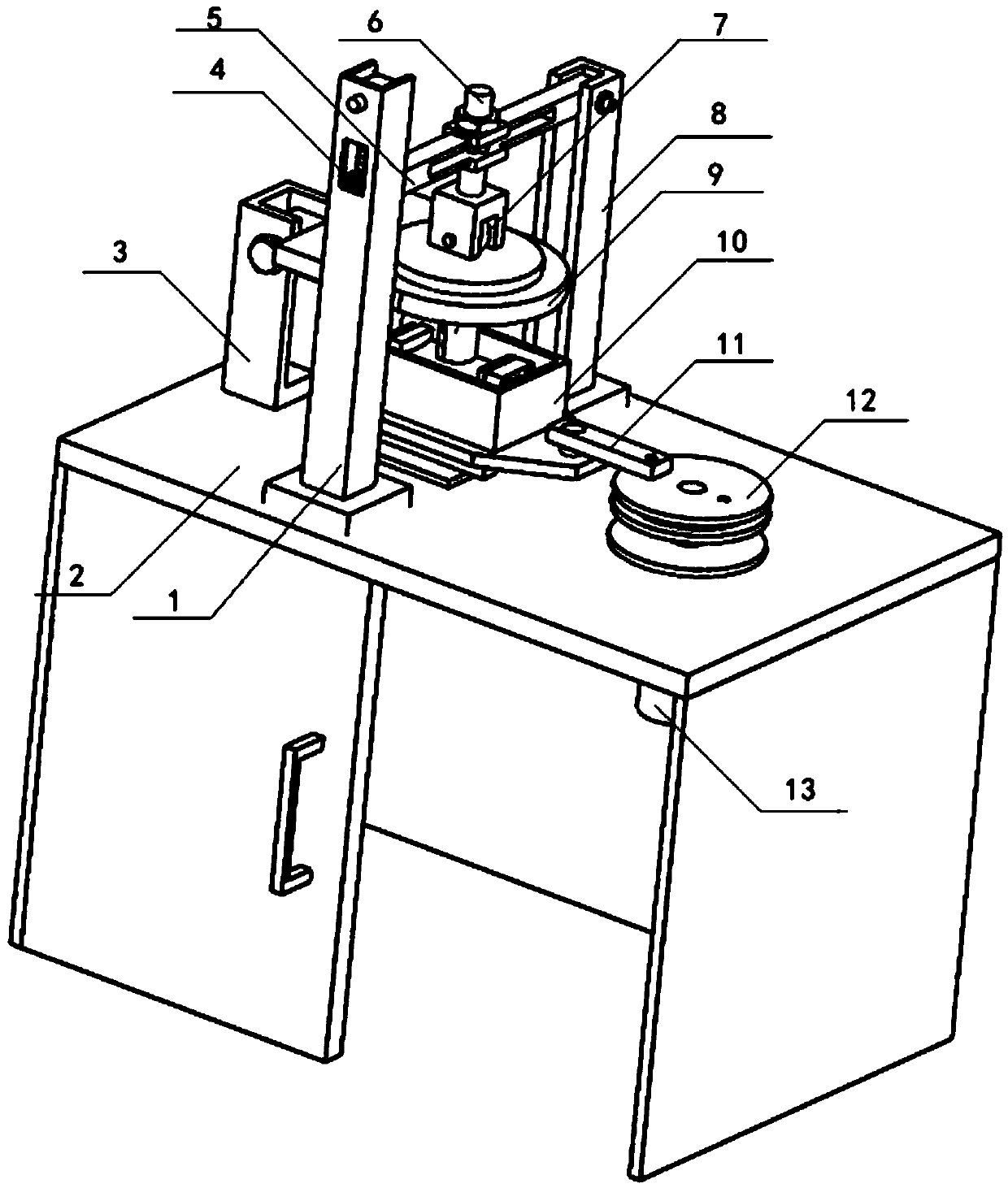
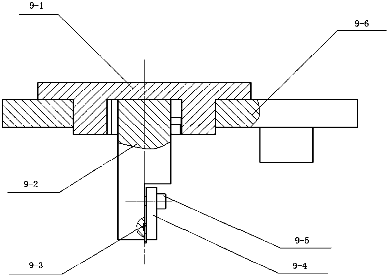
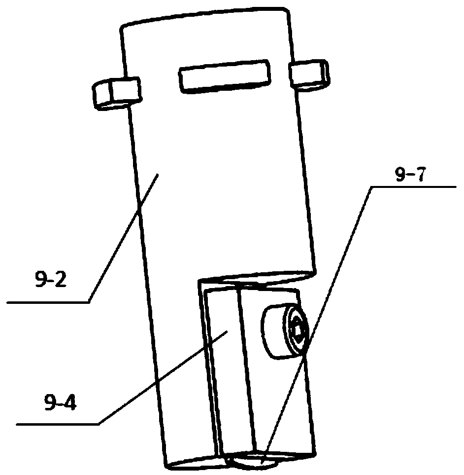
[0048] A multifunctional friction and wear test device of this embodiment includes a workbench 2, a variable loading assembly 4, an upper friction pair assembly 9, a reciprocating lower friction pair assembly 10, a pin-disk type lower friction pair assembly 14, and a crank disc 12 , spindle motor 13; front side, rear side and left side of workbench 2 are provided with front column 1, rear column 8 and side column 3 respectively, and crossbeam 5 is framed between front column 1 and rear column 8; Install on front column 1 There is a variable loading assembly 4, and one end of the rear column 8 and the crossbeam 5 is hinged and fixed by a pin, and the other end of the crossbeam 5 is connected to the variable loading assembly 4; the middle part of the crossbeam 5 is fixed with a loading rod 6, and the bottom of the loading rod 6 is connected with a roller 7. There is an upper friction pair assembly 9 under the roller 7; the upper friction pair assembly 9 is fixed on the side colum...


PUM


Abstract

The invention discloses a multifunctional friction wear testing device. The device comprises a workbench, a variable loading assembly, an upper friction pair assembly, a reciprocating type lower friction pair assembly, a pin disc type lower friction pair assembly, a crank disc and a spindle motor; a loading rod is fixed in the middle of a cross beam of the workbench; a roller wheel is connected tothe bottom of the loading rod; the upper friction pair component abutting against the roller wheel is arranged below the roller wheel; the upper friction pair assembly is fixed on a side surface stand column and is provided with an upper clamp used for fixing an upper sample piece; and the reciprocating type lower friction pair assembly or the pin disc type lower friction pair assembly is detachably fixed on the workbench below the upper friction pair assembly and is provided with a lower clamp used for fixing a lower sample piece. The two lower friction pair assemblies can be driven by the spindle motor and the crank disc, so that the utilization rate of equipment components is improved, and the overall cost of equipment is reduced; and multiple different friction tests can be realized,a load can be periodically changed, and a roller wheel balancing device ensures that external loading force is radially downward and acts on the upper sample piece.

Description

technical field [0001] The invention belongs to the technical field of friction test devices, and in particular relates to a multifunctional friction and wear test device. Background technique [0002] Due to the needs of modern industry, mechanical products are developing towards large-scale, high-speed, high-load and high-level automation, and higher and higher requirements are put forward for equipment reliability, precision retention, life extension, energy saving and cost reduction. These requirements are closely related to friction, wear and lubrication. Studies have shown that all machinery and equipment work relying on the relative motion of the friction pairs between their parts, and there must be friction and wear if there is relative motion. The friction and wear caused by improper lubrication not only affects the work and life of human beings, but also causes serious waste. In order to study the phenomenon of friction and wear and its essence, correctly evaluat...

Claims


Application Information

Patent Timeline
Patent Type & Authority Applications(China)
IPC IPC(8): G01N3/56G01N3/02
CPCG01N3/02G01N3/56
Inventor 姬翠翠盛战纪秀林曾文则沈梦茹
Owner HOHAI UNIV CHANGZHOU
Why Eureka
Try Eureka