Power battery high voltage relay control circuit and fault diagnosis method

A high-voltage relay and control circuit technology, applied in circuit breaker testing, instrumentation, electrical measurement, etc., can solve the problem that the battery control unit hardware architecture measurement and random hardware failure rate index are difficult to meet the safety integrity level and other problems

Pending Publication Date: 2019-03-29
CHINA FIRST AUTOMOBILE
View PDF0 Cites 19 Cited by
  • Summary
  • Abstract
  • Description
  • Claims
  • Application Information

AI Technical Summary

Problems solved by technology

[0005] The purpose of the present invention is to provide a power battery high-voltage relay control circuit and a fault diagnosis method, which solves the problem that the hardware architecture measur...

Method used


Image

  • Power battery high voltage relay control circuit and fault diagnosis method
  • Power battery high voltage relay control circuit and fault diagnosis method
  • Power battery high voltage relay control circuit and fault diagnosis method

Examples


Embodiment 1

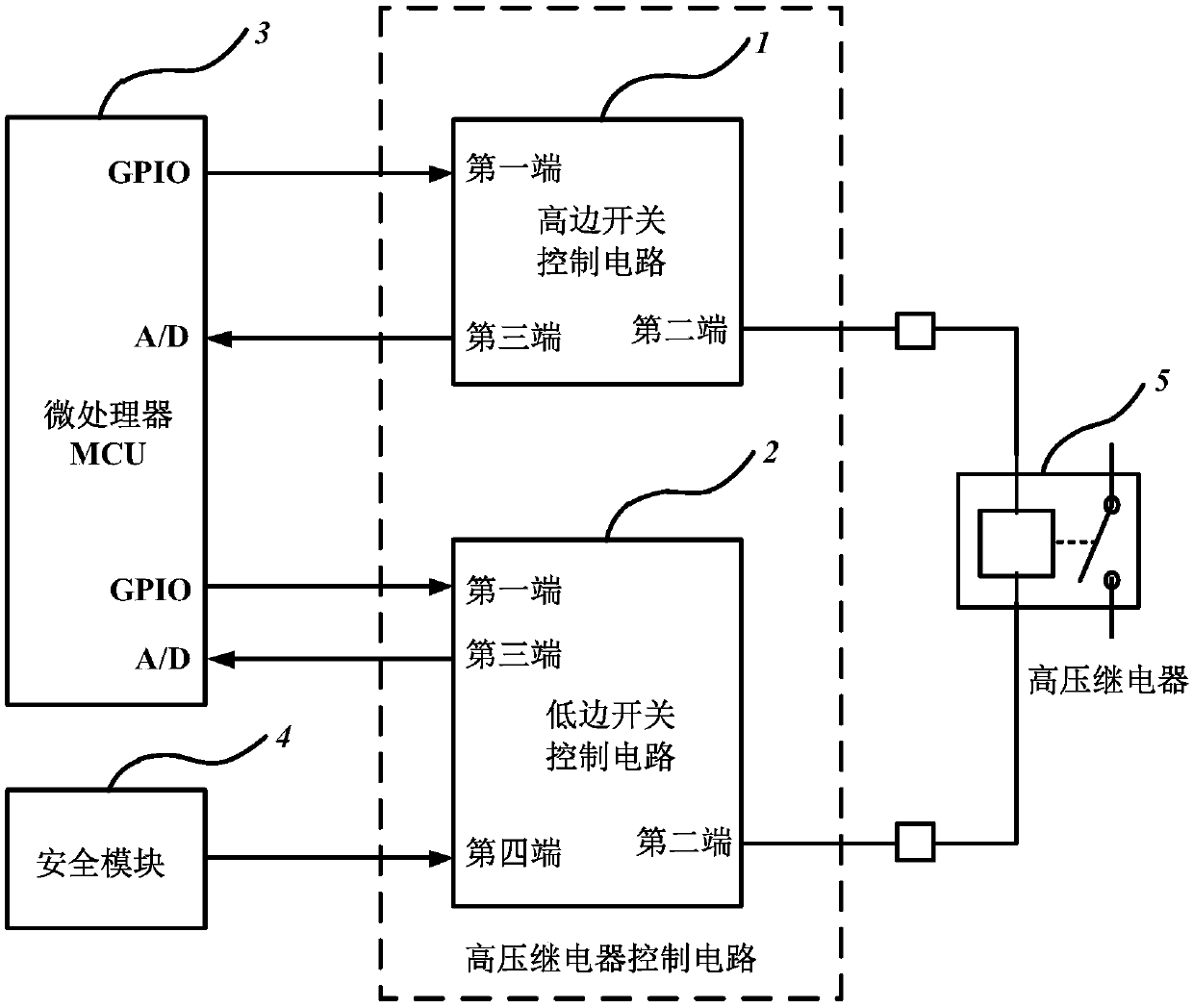
[0039] This embodiment provides a power battery high voltage relay control circuit, which includes a high-side switch control circuit 1 and a low-side switch control circuit 2 .

[0040] Such as image 3 As shown, the first end of the high-side switch control circuit 1 is connected to an output port of the MCU3, the second end of the high-side switch control circuit 1 is connected to one end of the coil of the high-voltage relay 5, and the first end of the high-side switch control circuit 1 Three terminals are connected to an A / D input port of the MCU; the first end of the low-side switch control circuit 2 is connected to an output port of the MCU, and the second end of the low-side switch control circuit 2 is connected to the other end of the coil of the high-voltage relay , the third end of the low-side switch control circuit 2 is connected to an A / D input port of the MCU, and the fourth end of the low-side switch control circuit 2 is connected to an output port of the secur...

Embodiment 2

[0053] This embodiment provides a fault diagnosis method for the power battery high-voltage relay control circuit, which is based on the relationship between the feedback voltage value of the A / D input port of the MCU and the diagnosis threshold voltage, and realizes the fault by combining the states of the high-side switch and the low-side switch. diagnostics, and includes fault diagnostics for the high-side switch control circuit and fault diagnostics for the low-side switch control circuit.

[0054] In this example, if Figure 6 As shown, the fault diagnosis of the high-side switch control circuit includes:

[0055] The MCU regularly reads the fault diagnosis signal V of the high-side switch control circuit 1 every 10ms. DIAGH ; Put the corresponding low-side switch control circuit in the conduction state, and judge whether the low-side switch control circuit fails, if the low-side switch control circuit fails, then end the fault diagnosis of the high-side switch control c...


PUM


Abstract

The invention discloses a power battery high voltage relay control circuit. The power battery high voltage relay control circuit is characterized by comprising a high side switch control circuit and alow side switch control circuit. The power battery high voltage relay control circuit comprises the high side switch control circuit and the low side switch control circuit, wherein the high side switch control circuit and the low side switch control circuit jointly control on or off of a high voltage relay, both the high side switch control circuit and the low side switch control circuit have adiagnosis circuit, so that fault diagnosis of a high side switch and a low side switch is realized according to a relationship between a fault diagnosis signal voltage and a diagnosis threshold voltage, faults like open circuit, short circuit to ground and short circuit to power supply can be determined and distinguished, and fault diagnosis coverage reaches up to 99%. Hardware architecture measurement and random hardware failure rate indexes meet security targets of security integrity level ASIL-C or ASIL-D.

Description

technical field [0001] The invention relates to the technical field of electronic control of electric vehicles, in particular to a control circuit and a fault diagnosis method for a high-voltage relay of a power battery of an electric vehicle. Background technique [0002] With the development of new energy vehicle technology, electric vehicles have become an important direction for the development of automotive technology. In electric vehicles, the safety performance of the power battery control system is the most important content of the performance of the vehicle. In the battery pack management system, the battery control unit is the core of the power battery control system, and the high-voltage relay controls whether the power battery outputs power to the drive system. [0003] The automotive safety integrity level of the battery pack management system is usually defined as ASIL-C or ASIL-D level (ASIL is the automotive safety integrity level, there are four levels, nam...

Claims


Application Information

Patent Timeline
IPC IPC(8): G01R31/327
CPCG01R31/3275
Inventor 隋建鹏王强闻继伟杨莉赵楠楠焦育成
Owner CHINA FIRST AUTOMOBILE
Why Eureka
Try Eureka