Phase-frequency calibration system and method of current sensor

A current sensor and calibration system technology, applied in the field of measuring instruments, can solve the problems of insufficient current phase measurement accuracy and power measurement accuracy, and achieve the effects of easy implementation, improved calibration efficiency, and high phase calibration accuracy

Inactive Publication Date: 2019-03-29
INNO INSTR (CHINA) INC
View PDF5 Cites 8 Cited by
  • Summary
  • Abstract
  • Description
  • Claims
  • Application Information

AI Technical Summary

Problems solved by technology

[0004] The phase-frequency calibration system and method of the current sensor of the present invention solve the technical problem that the power measuring instrument i

Method used


Image

  • Phase-frequency calibration system and method of current sensor
  • Phase-frequency calibration system and method of current sensor
  • Phase-frequency calibration system and method of current sensor

Examples


Embodiment Construction

[0051] In order to make the above objects, features and advantages of the present invention more comprehensible, specific implementations of the present invention will be described in detail below in conjunction with the accompanying drawings.

[0052] In the following description, numerous specific details are set forth in order to provide a thorough understanding of the present invention. However, the present invention can be implemented in many other ways different from those described here, and those skilled in the art can make similar extensions without violating the connotation of the present invention, so the present invention is not limited by the specific implementations disclosed below.

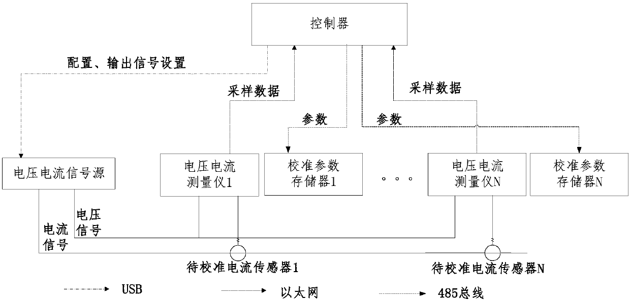
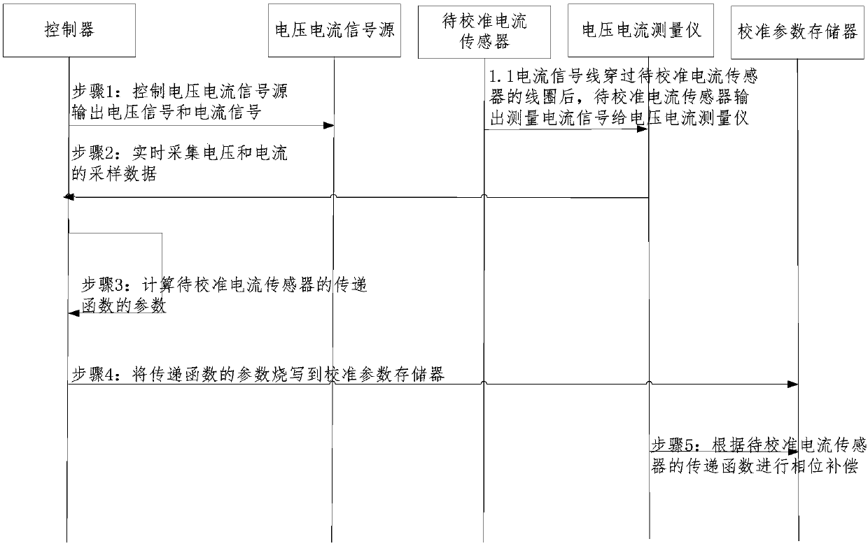
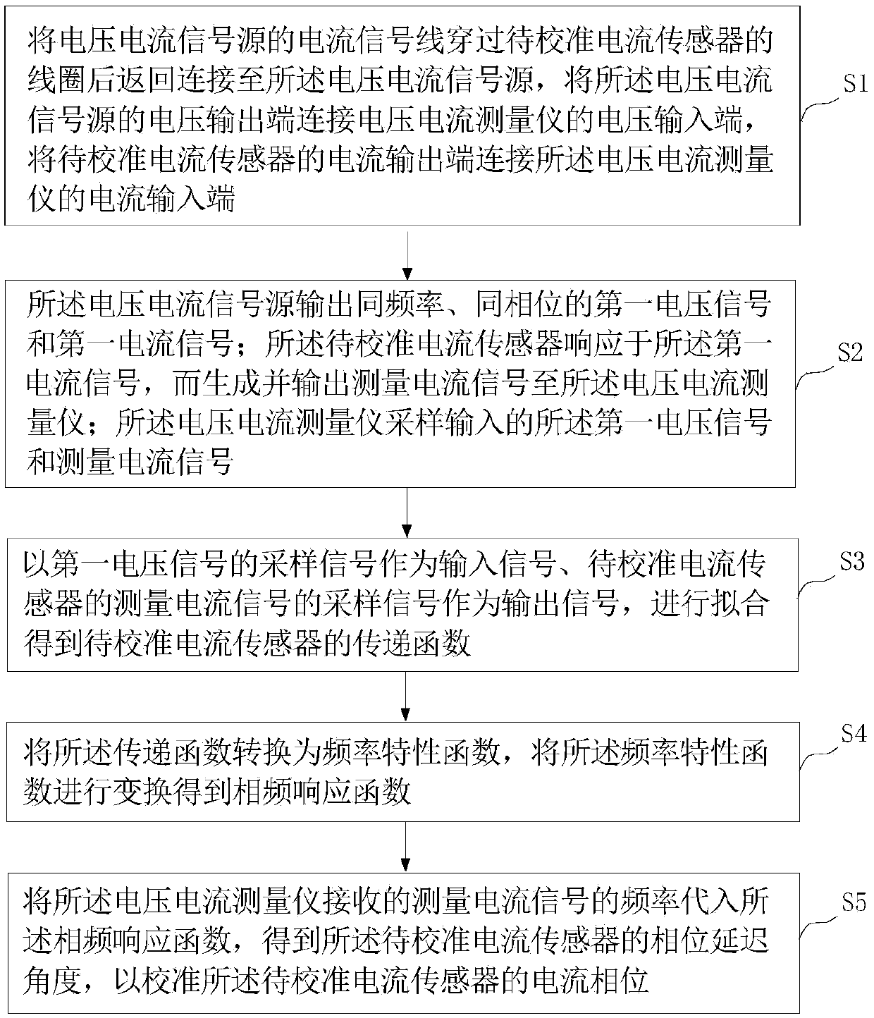
[0053] see figure 1 and figure 2 , the phase-frequency calibration system of the current sensor, including: voltage and current signal source, voltage and current measuring instrument, controller; the current signal line of the voltage and current signal source passes through the ...


PUM


Abstract

The invention provides a phase-frequency calibration system and method of a current sensor. A voltage and current signal source outputs a first voltage signal and a first current signal in the same phase and frequency; the current sensor to be calibrated outputs a measuring current signal in response to the first current signal; a voltage and current measuring instrument samples the first voltagesignal and the measuring current signal; an input signal, namely a sampling signal of the first voltage signal, and an output signal, namely, a sampling signal of the measuring current signal are fitto obtain a transfer function of the current sensor to the calibrated; the transfer function is converted into a frequency characteristic function, and further transformed to obtain a phase-frequencyresponse function; and the frequency of the measured measuring current signal is substituted into the phase-frequency response function to obtain a phase delay angle of the current sensor to be calibrated, and the current phase of the current sensor to be calibrated is calibrated. The technical problem that a phase error is introduced into the measuring current of the current sensor of a power measuring instrument and further the current pahse measuring precision and power measuring precision are not sufficiently high is solved.

Description

technical field [0001] The invention relates to the field of measuring instruments, in particular to a phase-frequency calibration system and method for a current sensor. Background technique [0002] Instruments with current phase measurement functions, such as power measuring instruments, power quality detectors, and power detection devices, usually measure indirectly through current sensors when measuring large currents that exceed the measuring range of the instrument. Due to the structure of the current sensor, the phase delay of the current will be caused, and the phase error introduced by the current sensor will greatly reduce the accuracy of the power measured by the measuring instrument. [0003] Since the phase error of the current sensor has an important impact on high-precision measuring instruments in measuring power, power event monitoring, and fault judgment, it is necessary to calibrate the phase error of the current sensor. Most of the current phase error c...

Claims


Application Information

Patent Timeline
IPC IPC(8): G01R35/00
CPCG01R35/005
Inventor 李楚元
Owner INNO INSTR (CHINA) INC
Why Eureka
Try Eureka