Preparation method of porous copper current collector, porous copper current collector, negative electrode and battery

A technology of porous copper and current collector, applied in the field of energy storage, can solve the problem of difficulty in ensuring the normal use of metal negative electrodes, and achieve the effects of low cost, uniform distribution and long cycle life

Active Publication Date: 2021-02-12
SHENZHEN GRADUATE SCHOOL TSINGHUA UNIV
View PDF1 Cites 1 Cited by
  • Summary
  • Abstract
  • Description
  • Claims
  • Application Information

AI Technical Summary

Problems solved by technology

Different from the traditional carbon negative electrode, because of a series of problems in the metal negative electrode, it is difficult for ordinary commercial copper foil to guarantee the normal use of the metal negative electrode. Therefore, higher requirements are put forward for the structure and properties of the current collector.

Method used


Image

  • Preparation method of porous copper current collector, porous copper current collector, negative electrode and battery
  • Preparation method of porous copper current collector, porous copper current collector, negative electrode and battery
  • Preparation method of porous copper current collector, porous copper current collector, negative electrode and battery

Examples


preparation example Construction

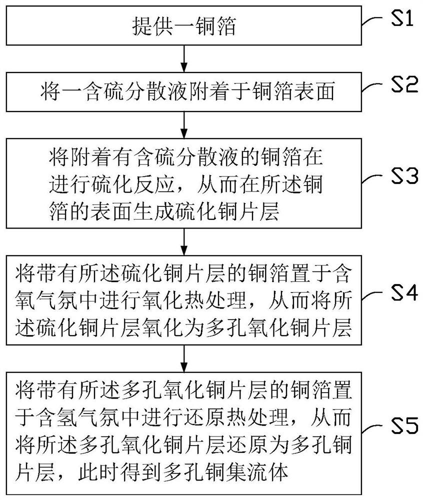
[0031] refer to figure 1 , a preferred embodiment of the present invention provides a method for preparing a porous copper current collector 100, the preparation method comprising the following steps:

[0032] Step S1, providing a copper foil;

[0033] Step S2, attaching a sulfur-containing dispersion to the surface of the copper foil;

[0034] Step S3, performing a vulcanization reaction on the copper foil attached with the sulfur-containing dispersion, thereby forming a copper sulfide sheet layer on the surface of the copper foil;

[0035] Step S4, placing the copper foil with the copper sulfide layer in an oxygen-containing atmosphere for oxidation heat treatment, so as to oxidize the copper sulfide layer into a porous copper oxide layer;

[0036] Step S5, placing the copper foil with the porous copper oxide layer in a hydrogen-containing atmosphere for reduction heat treatment, so as to reduce the porous copper oxide layer to a porous copper layer, and obtain a porous co...

Embodiment 1

[0050] Take a commercial copper foil with a thickness of 100 μm, and ultrasonicate it in ethanol for 30 minutes; dissolve sulfur powder, carbon black and PVDF in the solvent NMP with a mass ratio of 7:2:1, and prepare a sulfur-containing dispersion with a sulfur concentration of 10 mg / mL. liquid; drop the sulfur-containing dispersion liquid on the surface of copper foil, and control the sulfur load to be about 1 mg / cm 2 , Vulcanization reaction at 60°C for 24h; then put the copper foil in an air atmosphere, and carry out oxidation treatment at 600°C for 4h; place the oxidized copper foil in hydrogen / argon (5%H 2 +95% Ar) atmosphere, thermal reduction treatment at 500° C. for 2 hours, to obtain a porous copper current collector 100 .

Embodiment 2

[0052] The difference from Example 1 is that the concentration of the sulfur-containing dispersion in this example is 20 mg / mL, and the sulfur load on the surface of the copper foil is about 2 mg / cm 2 .

[0053] Other steps are the same as in Example 1 and will not be repeated here.


PUM

PropertyMeasurementUnit
thicknessaaaaaaaaaa
thicknessaaaaaaaaaa
diameteraaaaaaaaaa

Abstract

A method for preparing a porous copper current collector, comprising the following steps: providing a copper foil; attaching a sulfur-containing dispersion to the surface of the copper foil; performing a vulcanization reaction on the copper foil to which the sulfur-containing dispersion is attached; The copper foil is placed in an oxygen-containing atmosphere for oxidation heat treatment; the oxidized heat-treated copper foil is placed in a hydrogen-containing atmosphere for reduction heat treatment to obtain a porous copper current collector. The porous copper current collector prepared by this preparation method has a three-dimensional porous structure, and porous copper current collectors with different pore sizes and thicknesses can be prepared by changing the preparation parameters. The porous copper current collector prepared by the present invention is used as the negative electrode current collector. The battery has higher and more stable Coulombic efficiency and longer cycle life. The three-dimensional porous copper can effectively inhibit the formation and growth of dendrites in the negative electrode, and can achieve deep discharge.

Description

technical field [0001] The invention relates to the field of energy storage, in particular to a preparation method and application of a battery current collector. Background technique [0002] In recent years, the rapid development of mobile devices, electric vehicles, and smart grids has attracted a lot of attention and research on high-energy-density secondary batteries, especially secondary batteries such as lithium-ion batteries, sodium-ion batteries, and lithium-air batteries. A battery usually includes a metal negative electrode, a positive electrode (such as a ternary positive electrode, a sulfur positive electrode, an oxygen positive electrode), and a current collector. Metal anodes have high theoretical specific capacity and low reduction potential. However, there are a series of problems in metal anodes that limit its further development and practical application, such as uncontrollable dendrite growth in metal anodes, unstable interfacial reactions, severe volume...

Claims


Application Information

Patent Timeline
Patent Type & Authority Patents(China)
IPC IPC(8): H01M4/66H01M4/80H01M4/38H01M4/62
CPCH01M4/38H01M4/625H01M4/661H01M4/80Y02E60/10
Inventor 李宝华林逵秦显营徐晓富张哲旭康飞宇
Owner SHENZHEN GRADUATE SCHOOL TSINGHUA UNIV
Why Eureka
Try Eureka