Antenna structure and communication terminal

A technology of antenna structure and communication terminal, applied in the field of communication, can solve problems such as poor antenna performance

Active Publication Date: 2019-03-29
VIVO MOBILE COMM CO LTD
View PDF8 Cites 7 Cited by
  • Summary
  • Abstract
  • Description
  • Claims
  • Application Information

AI Technical Summary

Problems solved by technology

[0004] Embodiments of the present invention provide an antenna structure and a communication terminal to solve the problem of relatively poor antenna performance

Method used


Image

  • Antenna structure and communication terminal
  • Antenna structure and communication terminal
  • Antenna structure and communication terminal

Examples


Embodiment Construction

[0019] The following will clearly and completely describe the technical solutions in the embodiments of the present invention with reference to the accompanying drawings in the embodiments of the present invention. Obviously, the described embodiments are some of the embodiments of the present invention, but not all of them. Based on the embodiments of the present invention, all other embodiments obtained by persons of ordinary skill in the art without creative efforts fall within the protection scope of the present invention.

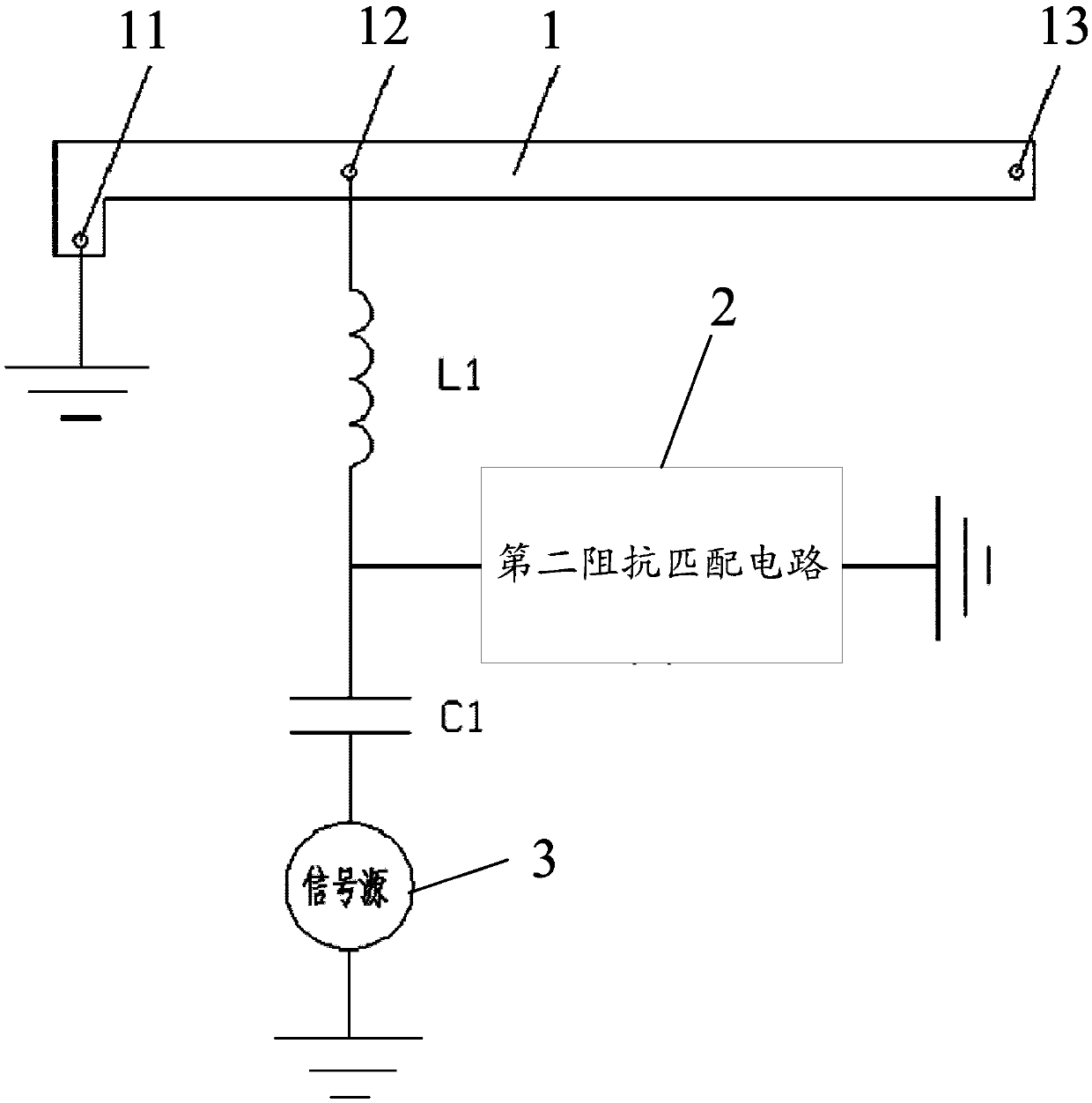
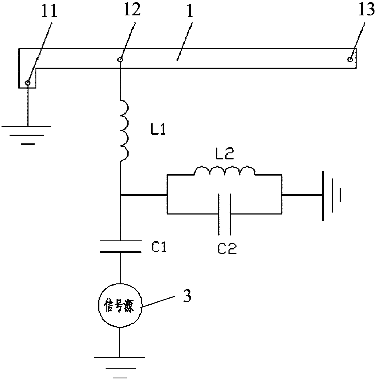
[0020] see figure 1 , figure 1 is a structural schematic diagram of the antenna structure provided by the embodiment of the present invention, such as figure 1 As shown, the antenna structure includes an antenna radiator 1, a first impedance matching circuit, a second impedance matching circuit 2 and a signal source 3; the first end 11 of the antenna radiator 1 is grounded, and the antenna radiator 1 is provided with A feed point 12, the distance bet...


PUM


Abstract

The invention provides an antenna structure and a communication terminal. The antenna structure comprises an antenna radiator, a first impedance matching circuit, a second impedance matching circuit and a signal source, wherein the first end of the antenna radiator is grounded, and the antenna radiator is provided with a feed point. The first impedance matching circuit comprises a first inductor and a first capacitor, wherein the first end of the first inductor is connected with the feed point, the second end of the first inductor is connected with the first end of the first capacitor, and thesecond end of the first capacitor is connected with the first end of the signal source. The first end of the second impedance matching circuit is connected with the second end of the first inductor,and the second end of the second impedance matching circuit is grounded. The second end of the signal source is grounded. The absolute value of the difference between the length of the antenna radiator and 1 / 4 wavelength of the first frequency band is smaller than a first specific value. Therefore, due to the first impedance matching circuit and the second impedance matching circuit, the voltage standing-wave ratio of the antenna can be reduced, the heat loss of the matching circuit can be reduced, and the performance of the antenna can be improved.

Description

technical field [0001] The invention relates to the technical field of communication, in particular to an antenna structure and a communication terminal. Background technique [0002] With the rapid development of terminal technology, communication terminals have become an indispensable tool in people's lives, and have brought great convenience to all aspects of users' lives. Communication terminals with a metal middle frame or an all-metal battery cover that are common in daily life are generally equipped with antennas, and the antennas can work in multiple frequency bands, such as 1.55-1.62GHz and 2.4-2.5GHz. Work. [0003] However, in the prior art, the VSWR of the antenna is relatively large, resulting in relatively poor performance of the antenna. Contents of the invention [0004] Embodiments of the present invention provide an antenna structure and a communication terminal, so as to solve the problem of relatively poor antenna performance. [0005] In order to so...

Claims


Application Information

Patent Timeline
Patent Type & Authority Applications(China)
IPC IPC(8): H01Q1/36H01Q1/50H01Q5/10H01Q5/28H01Q5/314H01Q5/328H01Q5/50H01Q1/24H01Q1/22
CPCH01Q1/22H01Q1/2258H01Q1/242H01Q1/36H01Q1/50H01Q5/10H01Q5/28H01Q5/314H01Q5/328H01Q5/50
Inventor 李日辉
Owner VIVO MOBILE COMM CO LTD
Why Eureka
Try Eureka