Easy-to-use busway

A busbar and busbar technology, which is applied in the field of busbars, can solve the problems of inserting a wire separator into a flame retardant separator, low use efficiency, and poor wire separators, and achieves high use efficiency, simple structure, and is conducive to heat dissipation. Effect

Active Publication Date: 2020-10-09
CHONGQING JINGLI ELECTRICAL APPLIANCE CO LTD
View PDF9 Cites 0 Cited by
  • Summary
  • Abstract
  • Description
  • Claims
  • Application Information

AI Technical Summary

Problems solved by technology

[0004] The technical problem to be solved by the present invention is that when the bus duct is in use, the wire separator cannot be inserted into the square hole of the flame-retardant partition well, and the use efficiency is low. Problems in fire retardant partitions

Method used


Image

  • Easy-to-use busway

Examples


Embodiment 1

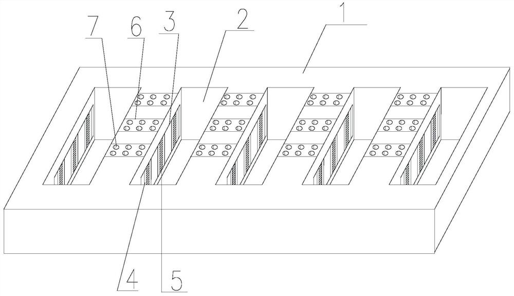
[0023] Such as figure 1 As shown, the easy-to-use busway of the present invention includes a busway body, and the busway body includes a flame-retardant partition 1 provided with several square holes 2 and a wire partition that runs through the square holes 2 and is vertically connected to the flame-retardant partition 1. board, a first placement groove 3 is arranged between two adjacent square holes 2 on the flame retardant partition 1, and a number of second placement grooves 4 are arranged on the first placement groove 3, and a number of second placement grooves 4 are arranged in the second placement groove 4. The rotating pulley 5, the axis of the pulley 5 is parallel to the plane where the flame retardant partition is located, and the diameter of the pulley 5 is the same as the distance between two adjacent square holes 2. When the wire partition is inserted into the square hole 2, The side of wire dividing plate contacts with pulley 5, and pulley 5 rotates under the driv...

Embodiment 2

[0025] For the easy-to-use busbar, on the basis of Embodiment 1, several convex lines are provided on the adjacent inner wall of the square hole 2 provided with the pulley 5 . In the flame-retardant partition 1, a heat dissipation layer 6 is arranged above the second placement groove 4, and a plurality of through holes 7 are arranged on the heat dissipation layer 6. One end of the through hole 7 runs through the upper end of the flame-retardant partition 1, and the other end of the through hole 7 One end runs through the lower end of the heat dissipation layer 6 and communicates with the second placement groove 4; the second placement groove 4 is also provided with a heat dissipation layer 6, and the heat dissipation layer 6 is provided with a plurality of through holes 7, and one end of the through hole 7 runs through the flame-retardant barrier. The lower end of the board 1 and the other end of the through hole 7 pass through the upper end of the heat dissipation layer 6 and ...

Embodiment 3

[0027] For the easy-to-use bus duct, on the basis of Embodiment 2, the number of second placement slots 4 in the first placement slot 3 is not less than three, and the axes of the pulleys 5 in the second placement slots 4 are on the same straight line. The pulley 5 is provided with a rubber layer.


PUM


Abstract

The invention discloses a novel bus duct convenient to use. A bus duct body includes a flame-retardant partition plates provided with a plurality of square holes, and conducting wire partition platespenetrating through the square holes and vertically connected to the flame-retardant partition plate. A first placement groove is disposed between two adjacent square holes on the flame-retardant partition plate; a plurality of second placement grooves are disposed on the first placement groove; rotatable pulleys are disposed in the second placement grooves; the axis of each of the pulleys is parallel to a plane of the flame-retardant partition plate; the diameter of each of the pulleys is the same as the distance between the adjacent two square holes; and when the conducting wire partition plates are inserted into the square holes, the conducting wire partition plates are in contact with side surfaces of the pulleys, and the pulleys are driven by the conducting wire partition plates to rotate. When the device is used, the novel bus duct is more convenient to quickly and conveniently insert the conducting wire partition plates into the square holes and can be effectively fixed after being stuck in, without affecting usage.

Description

technical field [0001] The invention relates to the field of bus ducts, in particular to bus ducts that are easy to use. Background technique [0002] The busway is a closed metal device composed of copper and aluminum busbar columns, which is used to distribute large power to various components of the decentralized system. It has increasingly replaced wires and cables in indoor low-voltage power transmission trunk line projects. The bus duct is a new type of conductor formed by using copper or aluminum as the conductor, supported by non-olefinic insulation, and then installed in the metal slot. Nowadays, it has become an indispensable wiring method in high-rise buildings, factories and other electrical equipment and power systems. Due to the power needs of various buildings such as buildings and factories, and this need has a tendency to increase year by year, using the original circuit wiring method, that is, the pipe-through method, brings many difficulties during const...

Claims


Application Information

Patent Timeline
Patent Type & Authority Patents(China)
IPC IPC(8): H02G5/06H02G5/10
CPCH02G5/06H02G5/10
Inventor 彭翔田力廖光明
Owner CHONGQING JINGLI ELECTRICAL APPLIANCE CO LTD
Why Eureka
Try Eureka