Adaptive Texture Gradient Prediction Method in Bandwidth Compression

A bandwidth compression and prediction method technology, applied in the field of compression, can solve problems such as poor correlation and small prediction residuals, and achieve the effects of improving accuracy, increasing bandwidth compression rate, and reducing theoretical limit entropy

Active Publication Date: 2021-05-18
XIAN CREATION KEJI CO LTD
View PDF7 Cites 0 Cited by
  • Summary
  • Abstract
  • Description
  • Claims
  • Application Information

AI Technical Summary

Problems solved by technology

[0004] In the existing texture correlation prediction method, for the macroblock (Macro block, referred to as MB) at the texture boundary in the image, since the current MB and the surrounding MB are not in the same texture area, the correlation between the current MB and the surrounding MB is relatively low. Poor, that is, the correlation between the current MB and the surrounding MB cannot be used to obtain a smaller prediction residual

Method used


Image

  • Adaptive Texture Gradient Prediction Method in Bandwidth Compression
  • Adaptive Texture Gradient Prediction Method in Bandwidth Compression
  • Adaptive Texture Gradient Prediction Method in Bandwidth Compression

Examples


Embodiment 1

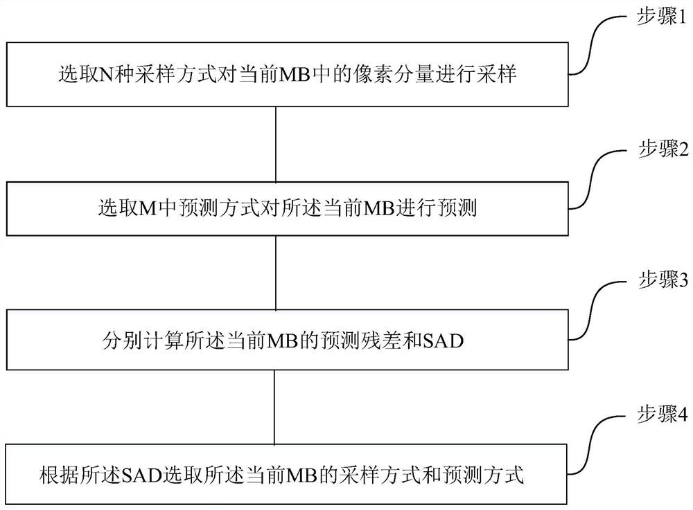
[0035] See figure 1 , figure 1 It is a schematic flow chart of an adaptive texture gradient prediction method in bandwidth compression provided by an embodiment of the present invention; this embodiment describes in detail a prediction method provided by the present invention, and the prediction method includes the following steps:

[0036] Step 1. Select N sampling methods to sample the pixel components in the current MB;

[0037] Step 2. Select the prediction mode in M ​​to predict the current MB;

[0038] Step 3. Calculate the prediction residual and SAD of the current MB respectively;

[0039] Step 4. Select the sampling mode and prediction mode of the current MB according to the SAD.

[0040] Wherein, step 1 may include the following steps:

[0041] Step 11. Select N non-equidistant sampling methods to sample the pixel components in the current MB, where N is an integer greater than 1.

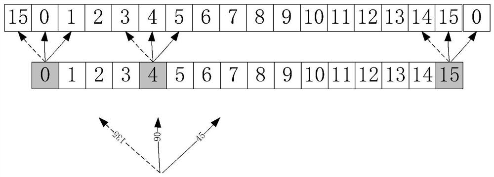
[0042] Preferably, the prediction method is an angle prediction method.

[0043...

Embodiment 2

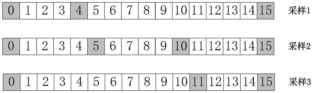
[0057] See figure 2 and image 3 , figure 2 A schematic diagram of a sampling method of another adaptive texture gradient prediction method provided by an embodiment of the present invention; image 3It is a schematic diagram of another adaptive texture gradient prediction method provided by an embodiment of the present invention. This embodiment describes in detail another prediction method proposed by the present invention on the basis of the foregoing embodiments. The forecasting method includes the following steps:

[0058] Step 1. Define the MB size

[0059] Define the size of MB as m*n pixel components, where m≥1, n≥1;

[0060] Preferably, the size of MB can be defined as 8*1 pixel component, 16*1 pixel component, 32*1 pixel component, 64*1 pixel component; in this embodiment, the size of MB is 16*1 pixel The component is used as an example for illustration, and the same applies to other MBs of different sizes. The pixel components in the MB are arranged sequent...


PUM


Abstract

The invention relates to a method for adaptive texture gradient prediction in bandwidth compression, which includes selecting N sampling methods to sample pixel components in the current MB; selecting M prediction methods to predict the current MB; and calculating the current MB respectively. The prediction residual and SAD; select the sampling mode and prediction mode of the current MB according to the SAD. The present invention calculates the prediction residual and SAD of the current prediction macroblock by defining the sampling mode of the MB. Compared with the existing methods, when the texture of the image to be compressed is more complex, for the MB at the texture boundary of the current image, according to the texture gradient principle, it does not depend on the surrounding MB of the current MB, but through the current MB The prediction residual obtained by its own texture characteristics can improve the accuracy of the prediction residual value for complex texture areas, further reduce the theoretical limit entropy, and increase the bandwidth compression rate.

Description

technical field [0001] The invention relates to the technical field of compression, in particular to an adaptive texture gradient prediction method in bandwidth compression. Background technique [0002] As TVs and monitors enter ultra-high-definition (4K) and ultra-high-definition (8K) resolutions, as well as the development and popularization of a new generation of cloud computing and information processing models and platforms with remote desktops as a typical form, the video image The demand for data compression is also moving towards higher resolution and composite images that include images captured by cameras and computer screen images, thus making the data volume of video images very large and requiring more storage space and transmission bandwidth. In this case Therefore, it is particularly necessary to use the bandwidth compression technology in the chip to improve the image storage space and transmission bandwidth. [0003] The original video signal has a huge am...

Claims


Application Information

Patent Timeline
Patent Type & Authority Patents(China)
IPC IPC(8): H04N19/132H04N19/159H04N19/182
CPCH04N19/132H04N19/159H04N19/182
Inventor 罗瑜张莹冉文方
Owner XIAN CREATION KEJI CO LTD
Why Eureka
Try Eureka