
Equipment debugging method, device and system, and storage medium

A debugging method and storage medium technology, applied in access restrictions, electrical components, wireless communication, etc., can solve the problems of low automation, slow data transmission speed, and long time consumption, and achieve high automation, increase data transmission speed and The effect of debugging efficiency and convenient debugging

Active Publication Date: 2019-03-29
GUANGDONG VANWARD NEW ELECTRIC CO LTD
View PDF8 Cites 7 Cited by
  • Summary
  • Abstract
  • Description
  • Claims
  • Application Information

AI Technical Summary

Problems solved by technology

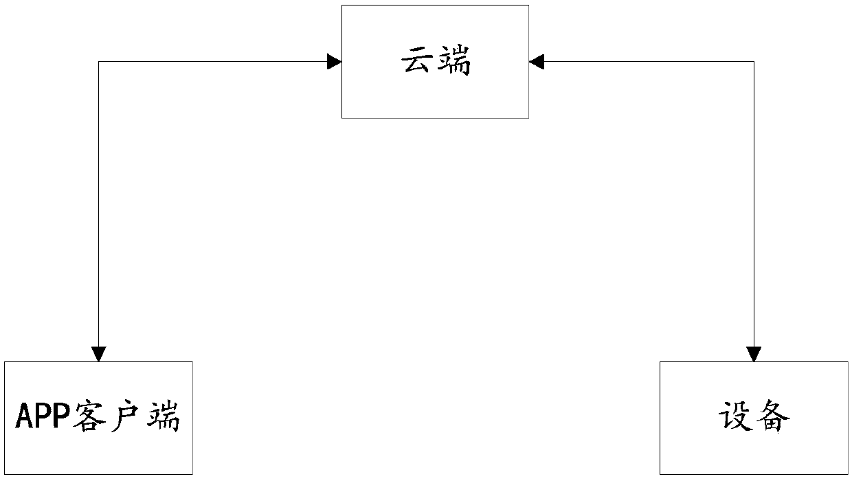
[0002] In the prior art, the commissioning of home appliances generally uses transparent transmission technology for communication connection, such as figure 1 As shown, first, the device and the user's APP client are connected to the wireless network or mobile data network of the Internet through their own wireless functions, and the connection between the APP client and the device has been established; then the APP client sends debugging instructions through the Internet. to the cloud; the cloud forwards it to the device after receiving the debugging command from the APP client; the device runs according to the debugging command after receiving the debugging command from the APP client, and sends the running result to the cloud; the cloud receives the running command uploaded by the device The results are then forwarded to the APP client to realize the debugging of the device by the APP client; and the whole communication debugging process must be realized under a specific connected Internet, the data transmission speed is slow, time-consuming, complicated process and low efficiency , and each device must be connected to the Internet one by one through manual operation, and the degree of automation is low

Method used


Image

  • Equipment debugging method, device and system, and storage medium
  • Equipment debugging method, device and system, and storage medium
  • Equipment debugging method, device and system, and storage medium

Examples


Embodiment Construction

[0042] The following will clearly and completely describe the technical solutions in the embodiments of the present invention with reference to the accompanying drawings in the embodiments of the present invention. Obviously, the described embodiments are only some, not all, embodiments of the present invention. The embodiments of the present invention and all other embodiments obtained by persons of ordinary skill in the art without creative efforts all belong to the protection scope of the present invention.

[0043] see figure 1 , the first embodiment of the present invention provides a device debugging method, which is executed by a terminal device installed with a client, and specifically includes the following steps:

[0044] In the embodiment of the present invention, the client is an application program installed on a terminal device, and the terminal device can be a computing device with a WIFI communication module such as a computer, a mobile phone, a tablet computer...


PUM


Abstract

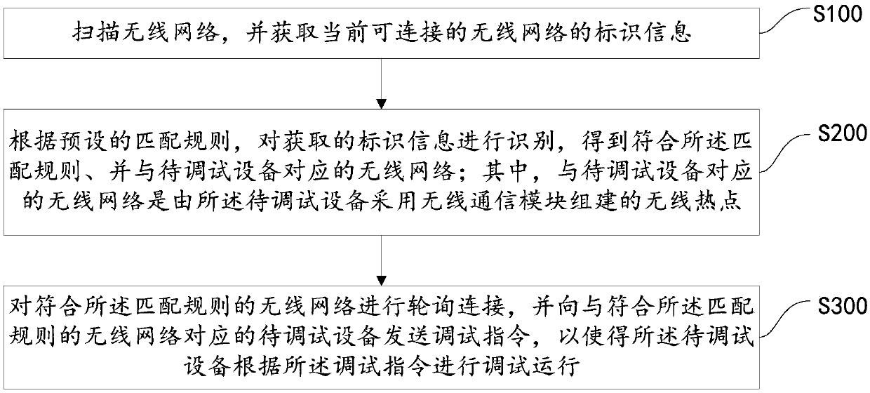
The invention discloses an equipment debugging method, device and system, and a storage medium. The method comprises the steps of scanning an wireless network, and acquiring identifier information ofa currently connectable wireless network; recognizing the acquired identifier information according to a preset matching rule to acquire the wireless network corresponding to equipment to be debuggedaccordant with the matching rule, wherein the wireless network corresponding to the equipment to be debugged is a wireless hotspot built by the equipment to be debugged through using a wireless communication module; and polling and connecting the wireless network accordant with the matching rule, and sending a debugging command to the equipment to be debugged corresponding to the wireless networkaccordant with the matching rule, thus allowing the equipment to be debugged to perform debugging and running according to the debugging command. The client and the equipment do not need to be connected with the Internet, the data transmission speed and the debugging efficiency can be effectively improved, meanwhile, the whole debugging process dose not need artificial participation, the automaticcommunication connection and automatic debugging of the client and the debugging equipment are achieved, and the automation degree of equipment debugging is high.

Description

technical field [0001] The invention relates to the technical field of equipment debugging, in particular to an equipment debugging method, device, system and storage medium. Background technique [0002] In the prior art, the commissioning of home appliances generally uses transparent transmission technology for communication connection, such as figure 1 As shown, first, the device and the user's APP client are connected to the wireless network or mobile data network of the Internet through their own wireless functions, and the connection between the APP client and the device has been established; then the APP client sends debugging instructions through the Internet. to the cloud; the cloud forwards it to the device after receiving the debugging command from the APP client; the device runs according to the debugging command after receiving the debugging command from the APP client, and sends the running result to the cloud; the cloud receives the running command uploaded by...

Claims


Application Information

Patent Timeline
Patent Type & Authority Applications(China)
IPC IPC(8): H04W24/02H04W24/04H04W48/16H04W74/06H04W76/14
CPCH04W24/02H04W24/04H04W48/16H04W74/06H04W76/14
Inventor 卢宇聪黎嘉明邓卓汶黄建优
Owner GUANGDONG VANWARD NEW ELECTRIC CO LTD
Learn More