Roll shaft used for brush roll

A roller shaft and brush roller technology, used in applications, household appliances, suction nozzles, etc., can solve problems such as fatigue failure and stress concentration, and achieve the effect of reducing the dynamic stress concentration factor, eliminating high stress concentration and extending the service life.

Pending Publication Date: 2019-04-02
常熟市雷得双金属复合管业有限公司
View PDF0 Cites 0 Cited by
  • Summary
  • Abstract
  • Description
  • Claims
  • Application Information

AI Technical Summary

Problems solved by technology

[0004] In view of this, the purpose of the present invention is to provide a roller shaft used for brush rollers, to solve the problem that the existing brush roller roller shaft slots are prone to stress concentration and cause fatigue failure

Method used


Image

  • Roll shaft used for brush roll
  • Roll shaft used for brush roll
  • Roll shaft used for brush roll

Examples


Embodiment Construction

[0030] The specific implementation manners of the present invention will be further described below in conjunction with the accompanying drawings, so as to make the technical solution of the present invention easier to understand and grasp.

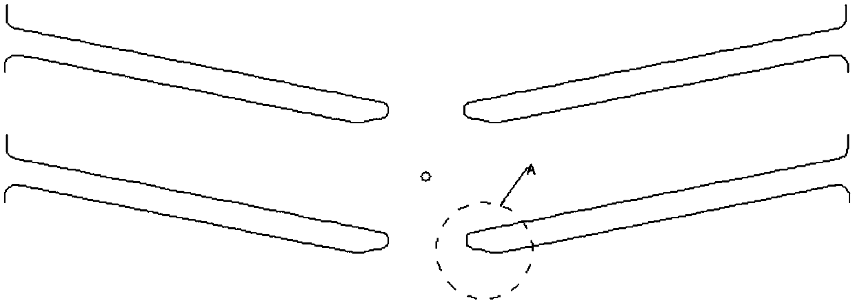
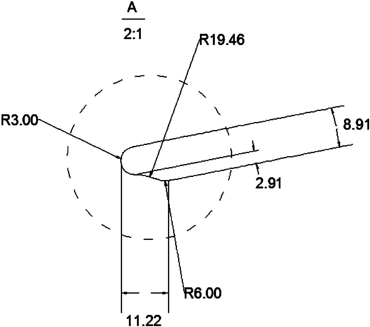
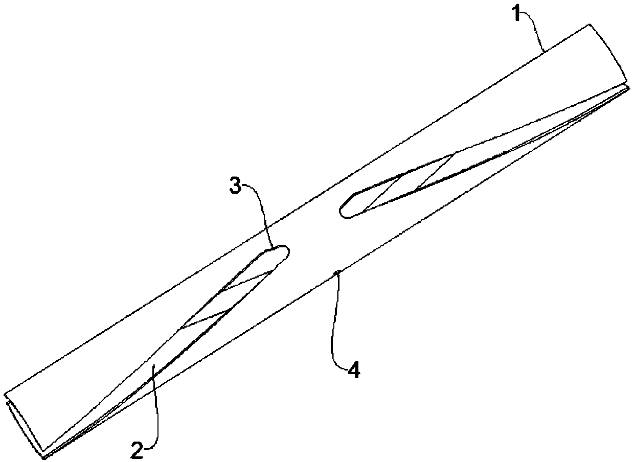
[0031] Figure 4 It shows the groove structure of the general roller shaft on the market, and its end adopts a single arc transition structure. During the working process of this structure, especially at the dynamic moment of starting or receiving impact, the intersection of the helix and the arc section is equivalent to a A smooth transition notch, resulting in stress concentration at this place, will lead to crack initiation and propagation during repeated use, and eventually fatigue failure, as follows:

[0032] 1. If Figure 5 As shown, assuming that the brush roller bears a uniformly distributed load of 60 lbs, when its full cross-section is stressed,

[0033] Stress level P=F / S=60*0.4S4*9.8 / 12S*1=2.14MPa;

[0034] Referring to th...


PUM


Abstract

The invention provides a roll shaft used for a brush roll. The roll shaft comprises a shaft body, at least one groove part spirally extending is arranged on the peripheral surface of the shaft body for fixing a brush bar, at least one end part of the groove part adopts continuous curve transition, preferably, a three-arc transition structure is adopted, by changing the structure with one arc transition line at the end part of the groove part, the highly concentration phenomenon of stress can be eliminated, so that the bearing force is improved, and the service life of the roll shaft is prolonged.

Description

technical field [0001] The invention relates to the technical field of vacuum cleaners, in particular to a roller shaft used for brush rollers. Background technique [0002] The vacuum cleaner is a commonly used cleaning tool. Its operating principle is to push the air to the side of the air outlet of the vacuum cleaner through the high-speed rotation of the internal impeller, so that the air pressure on the side of the air inlet is lower than the external ambient air pressure of the vacuum cleaner. Air flows into the body from the air inlet of the vacuum cleaner. The suction head of the vacuum cleaner usually includes a brush roller and a brush placed on the brush roller. When working, the brush roller drives the brush to rotate, rolling up dust and other foreign objects on the surface to be cleaned. To make it inhaled, usually, the brush will be bent at a certain angle in a spiral shape, so that there will be more contact with the ground during work, the cleaning area will...

Claims


Application Information

Patent Timeline
IPC IPC(8): A47L9/04
CPCA47L9/0444
Inventor 吕洲
Owner 常熟市雷得双金属复合管业有限公司
Why Eureka
Try Eureka