Stationary shaft shoulder friction stir welding method capable of coaxially adding materials by forming groove

A technology of friction stir welding and static shoulder, which is applied in the field of welding and static shoulder friction stir welding, can solve the problems of stress concentration, joint flash, weld thinning, etc., and achieve a wide range of applicable materials and improve applicability , to avoid the effect of metal inclusions

Inactive Publication Date: 2019-04-02
SHANGHAI AEROSPACE EQUIP MFG GENERAL FACTORY
View PDF7 Cites 9 Cited by
  • Summary
  • Abstract
  • Description
  • Claims
  • Application Information

AI Technical Summary

Problems solved by technology

[0006] The purpose of the present invention is to solve the problems such as inability to add welding material coaxially, joint flash, local thinning of weld seam, and stress concentration in the traditional friction stir welding process, and propose a static axis for coaxially adding materials for bevelling In the shoulder friction stir welding method, a U-shaped groove (12) is provided on the base metal (10) to be welded and placed under the stirring tool; the stirring tool includes a stirring pin (6) and a stationary shoulder (8), and the The static shoulder (8) is fixed on the main shaft base (5), and the section of the end of the stirring needle (6) is smaller than the section of the U-shaped groove (12); the stirring needle (6) is rotated at a high speed while being Apply axial force and keep feeding downwards, when the stirring pin (6) rotates at high speed on the base material (10) to be welded to generate frictional heat, and at the same time, the stirring tool advances along the direction of the weld, the stationary The rear edge of the shoulder (8) is provided with a forced forming groove (13) with a round corner transition, so that the fillet weld of the base metal (10) to be welded has the same smooth transition outer contour as the shape of the forced forming groove (13); Under the upsetting pressure of the static shoulder (8), the base metal to be welded (10) is released from the forced forming groove (13), and a U-shaped slope is arranged on the front edge of the static shoulder (8). The shape of the mouth (12) matches the constraint of the constrained cavity to form the weld

Method used


Image

  • Stationary shaft shoulder friction stir welding method capable of coaxially adding materials by forming groove
  • Stationary shaft shoulder friction stir welding method capable of coaxially adding materials by forming groove
  • Stationary shaft shoulder friction stir welding method capable of coaxially adding materials by forming groove

Examples


Embodiment

[0021] The present invention will be described in more detail below with reference to the accompanying drawings. These examples are only descriptions of the best embodiments of the present invention, and do not limit the scope of the present invention in any way. The present invention will be further described in detail below in conjunction with the accompanying drawings and specific embodiments.

specific Embodiment approach 1

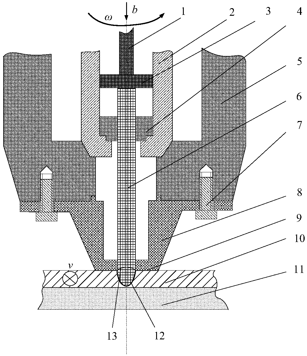
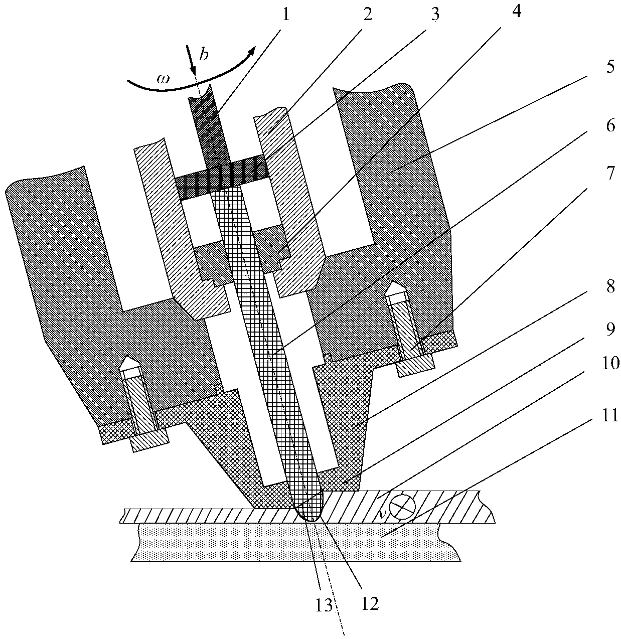
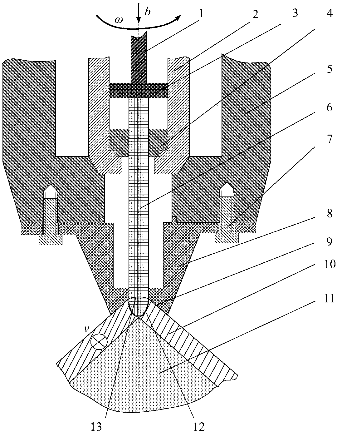
[0022] Specific implementation mode one: the following combination figure 1 , figure 2 , image 3 To describe this embodiment, figure 1 Shown is a schematic diagram of static shoulder friction stir welding of flat butt grooved coaxial filling materials. A U-shaped groove 12 is made on the base metal to be welded. The stirring tool is composed of a rotating stirring pin 6 and a stationary shoulder 8. The static shoulder 8 is fixed on the main shaft base 5, the stirring pin 6 is composed of the same material as the base metal 10 to be welded, and the end of the stirring pin is processed into a shape slightly smaller than the U-shaped groove 12 section size. During welding, the stirring pin 6 rotates at a high speed at a speed ω, and at the same time exerts an axial force on the stirring pin 6 and maintains a downward feed speed b. When the stirring pin 6 contacts the base material 10 to be welded, friction heat generation begins, and the friction area on the contact surface ...


PUM


Abstract

The invention provides a stationary shaft shoulder friction stir welding method capable of coaxially adding materials by forming a groove. A U-shaped groove is formed in a base material to be welded,a stationary shaft shoulder is fixed to a main shaft base body, a stirring needle is composed of the same material as the base material to be welded, and the end of the stirring needle is machined into a shape slightly smaller than the section size of the U-shaped groove. Heat is produced by friction when the stirring needle is in contact with the base material to be welded, and meanwhile, a stirring tool keeps moving in the direction of a welding seam. A restrained cavity matched with the shape of the groove of the base material is designed in the front edge of the stationary shaft shoulder of the stirring tool so that the flowing welding seam material cannot emerge from the front end of the shaft shoulder. According to the stationary shaft shoulder friction stir welding method capable ofcoaxially adding the materials by forming the groove, the welding materials can be coaxially added, the joint strength is strengthened, meanwhile, the stationary shaft shoulder technology is adoptedin a combination mode, and the problems that in the traditional friction stir welding process, the welding materials cannot be coaxially added, joint material thinning exists, the joint has differentthicknesses, and the welding difficulty of an angle joint is large are solved.

Description

technical field [0001] The invention belongs to the field of welding, and in particular relates to the field of static shoulder friction stir welding with grooved coaxial additive materials. Background technique [0002] In recent years, friction stir welding technology, as a solid-phase joining technology, has been widely promoted and applied in the fields of aviation, aerospace, automobiles, ships, and rail transit. It provides an effective solution for the welding of aluminum, magnesium, copper and other non-ferrous metals. [0003] The traditional friction stir welding technology mostly welds without adding materials. The weld material comes from the base metal to be welded. Due to the influence of internal micro-defects, welding flash, and local thinning of the weld, there is a certain degree of local strength of the weld. weakened. The British Institute of Welding separates the shoulder from the stirring needle on the basis of traditional friction stir welding, and p...

Claims


Application Information

Patent Timeline
Patent Type & Authority Applications(China)
IPC IPC(8): B23K20/12
CPCB23K20/122
Inventor 赵慧慧尹玉环胡蓝高嘉爽封小松董吉义郭立杰
Owner SHANGHAI AEROSPACE EQUIP MFG GENERAL FACTORY
Why Eureka
Try Eureka