Bicycle gear shifter and bicycle

A bicycle and gear shifter technology, which is applied to bicycle accessories, bicycle gear shifting mechanisms, transportation and packaging, etc., can solve the problems of insufficient compact structure, poor linkage, complex structure, etc., so as to improve the reliability of shifting gears and reduce production costs. , the effect of reducing manufacturing costs

Pending Publication Date: 2019-04-02
ZHUHAI L-TWOO SPORT TECH CO LTD
View PDF2 Cites 3 Cited by
  • Summary
  • Abstract
  • Description
  • Claims
  • Application Information

AI Technical Summary

Problems solved by technology

[0003] However, the positioning pawl and the release pawl of some existing bicycle shifters are arranged separately, and the ratchet set needs to be respectively provided with a positioning ratchet cooperating with the positioning pawl and a release ratchet cooperating with the release pawl, resulting in The structure is not compact enough, the linkage is poor, it takes up a lot of space, the structure is complex and the production cost is high
In a bicycle shifting device disclosed in Chinese patent document CN1097542C, although the shifter integrally forms the positioning pawl and the release pawl into a pawl member, and integrates the positioning ratchet and the release ratchet into a universal ratchet, but due to the The two ratchets of the pawl member are both arranged on one side of the mating ratchet, so that only one end of the pawl member and the mating ratchet on the ratchet are stressed, which will easily cause the pawl member to deviate from the rotating shaft connected to itself. Therefore, an additional holding plate needs to be provided to assist in fixing the ratchet and the pawl member, which increases the structural complexity of the bicycle shifter
A bicycle transmission of Chinese patent document CN1765694B, the ratchet of the transmission is provided with three rows of teeth, two rows of teeth are matched with the positioning pawl and the release pawl of the pawl member, and the other row of teeth is matched with the push pawl of the push rod. Cooperate, this increases the complexity of the ratchet manufacturing, and increases the volume and cost of the ratchet

Method used


Image

  • Bicycle gear shifter and bicycle
  • Bicycle gear shifter and bicycle
  • Bicycle gear shifter and bicycle

Examples


Embodiment Construction

[0034]The bicycle includes a vehicle frame, a derailleur, a speed change line and a bicycle shifter 100. The derailleur is installed on the rear chainstay of the vehicle frame or in the middle of the vehicle frame, and the first end of the speed change line is connected with the derailleur.

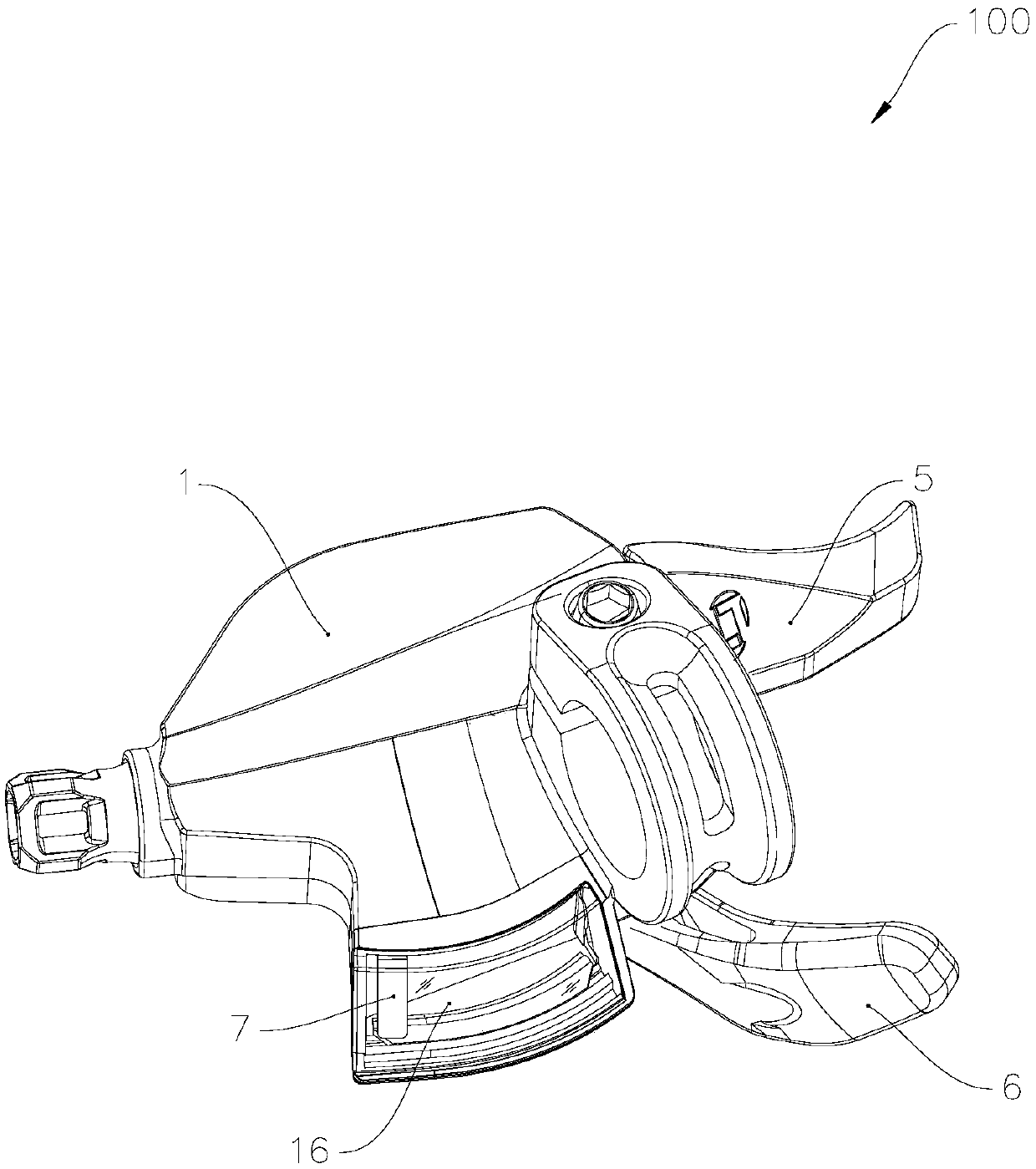
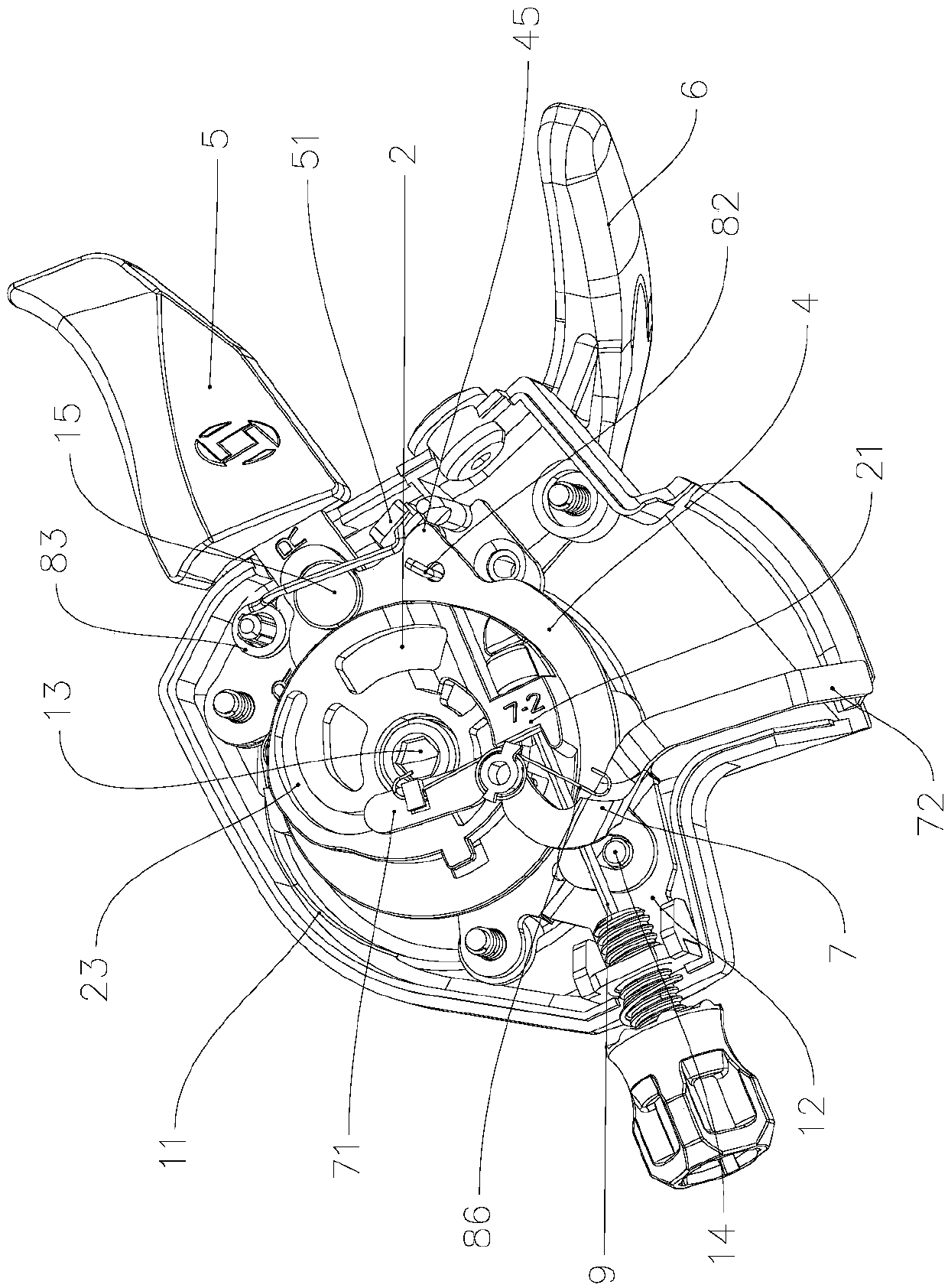
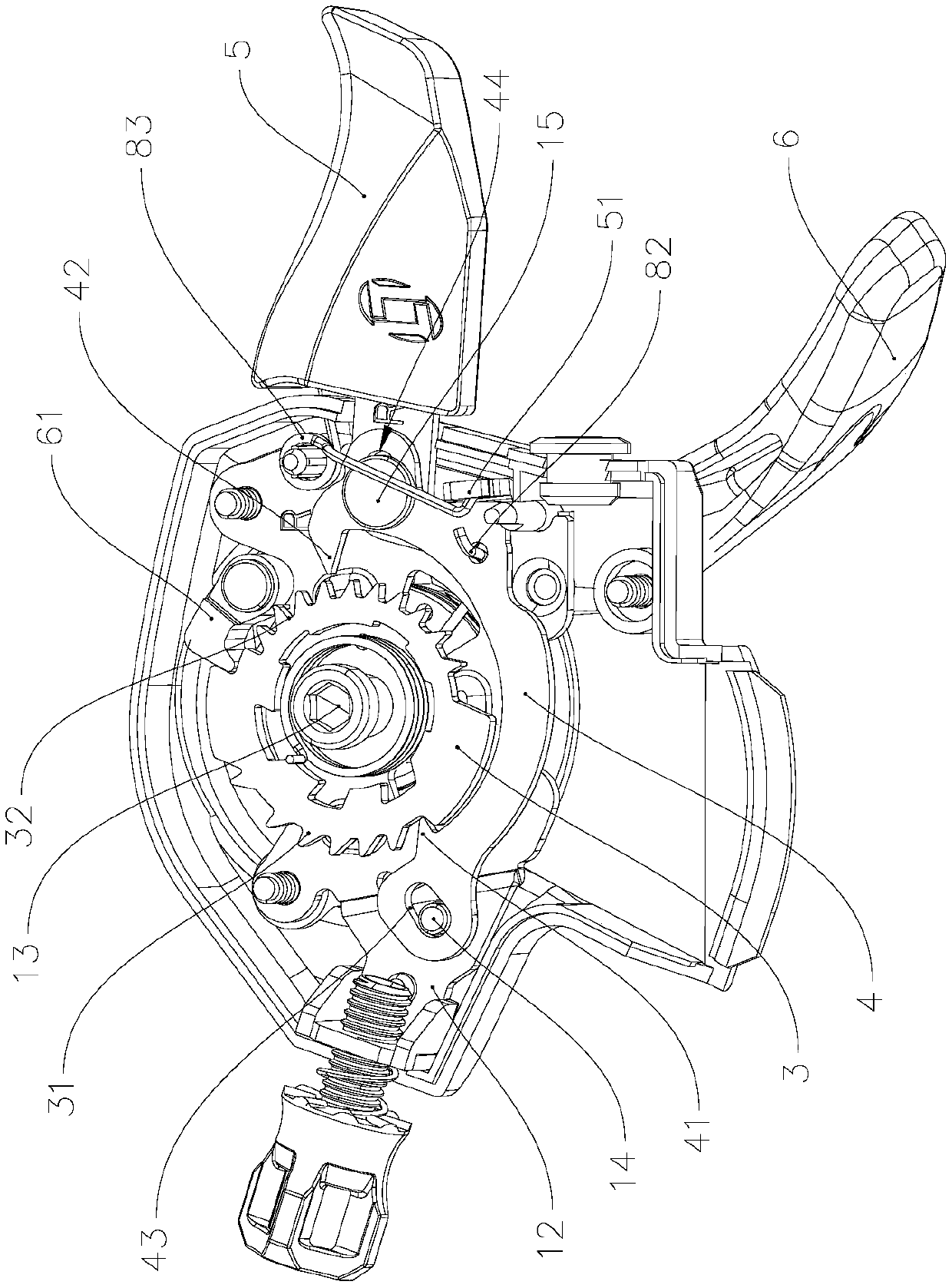
[0035] refer to Figure 1 to Figure 3 , The bicycle shifter 100 includes a housing 1 , a winding member 2 , a ratchet 3 , a pawl member 4 , a release lever 5 , a push rod 6 and an indication member 7 . Wherein, the housing 1 is installed on the handle of the vehicle frame. The housing 1 includes an upper housing and a lower housing, and an accommodating cavity 11 is formed between the upper housing and the lower housing. A bracket 12 is fixedly installed on the lower housing, the bracket 12 is located in the receiving cavity 11 , and a rotating shaft 13 is arranged on the bracket 12 .

[0036] combine Figure 4 , the winding member 2 is sleeved on the rotating shaft 13 , and the winding...


PUM


Abstract

The invention provides a bicycle gear shifter and a bicycle. The bicycle gear shifter includes a housing internally provided with a bracket, a winding member rotatably mounted on a rotating shaft of the bracket, a ratchet wheel sleeving the winding member, a pawl member positioned at the circumference of the ratchet wheel and movably connected to the bracket, a release lever and a push lever rotatably connected to the rotating shaft. The ratchet wheel is provided with a first tooth portion and a second tooth portion at the circumference, a positioning pawl disposed toward the first tooth portion and a release pawl disposed toward the second tooth portion are arranged at the both ends of the pawl member, the positioning pawl and the release pawl are located on opposite sides of the ratchetwheel, the release lever is hinged to the bracket and can poke the pawl member to slide relative to the bracket, so that the positioning pawl is engaged or disengaged with the first tooth portion, andthe release pawl is engaged or disengaged with the second tooth portion, a push pawl is hinged to the push lever, and the push lever can drive the push pawl to be engaged with the second tooth portion. The bicycle gear shifter and the bicycle have the advantages of simple structure and reliable operation.

Description

technical field [0001] The invention relates to the technical field of bicycles, in particular to a bicycle shifter and a bicycle using the shifter. Background technique [0002] The shift structure of the existing bicycle shifter usually includes a ratchet set, a positioning pawl and a release pawl, wherein the ratchet set includes a positioning ratchet and a release ratchet which rotate synchronously. When the bicycle is in reverse gear operation, the positioning pawl rotates and releases the locking of the current position of the positioning ratchet, so that the ratchet group retreats under the action of the return spring, and when the ratchet group retreats, the release pawl moves toward the release ratchet. Move until it engages with the release ratchet, so as to ensure that the positioning ratchet will not retreat after retracting one tooth position. When the positioning pawl is reset, the positioning pawl is re-engaged with a new tooth position of the positioning rat...

Claims


Application Information

Patent Timeline
Patent Type & Authority Applications(China)
IPC IPC(8): B62M25/04
CPCB62M25/04
Inventor 彭国鹏钱后平汤道军刘春生
Owner ZHUHAI L-TWOO SPORT TECH CO LTD
Why Eureka
Try Eureka