

Composite material rotary body butt joint
A composite material and butt joint technology, applied in the direction of combustion of the air inlet of the power plant, can solve the problems of large end deformation, difficult dimensional tolerance control, and inability to guarantee the shape tolerance in the docking area, so as to reduce the deformation and rebound. , Guarantee the effect of internal adjective
- Summary
- Abstract
- Description
- Claims
- Application Information
AI Technical Summary
Problems solved by technology
Method used
Image

Examples
Embodiment Construction
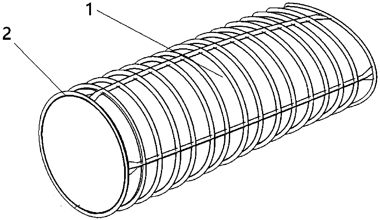
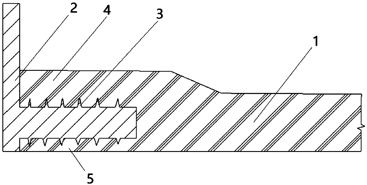
[0012] Referring to the accompanying drawings, the butt joint of the composite material revolving body of the present application includes a revolving body body 1 and a metal butt flange 2 made of composite materials. Its special innovation is that during the forming process of the revolving body body 1, the The quasi-revolving end of the metal butt joint flange 2 is embedded in the end portion of the revolving body 1 of composite material. This structure is particularly suitable for large-scale composite material-like gyrostructures such as aircraft inlets. In order to increase the bonding strength between the butt flange 2 made of metal material and the quasi-revolver structure made of composite material, it is preferable to provide a plurality of tooth-shaped protrusions 3 on both side walls of the revolving end of the metal butt flange. During the paving process of the quasi-rotary body 1, the inner paving layer 4 of the end of the quasi-rotary body 1 is laid on the inner ...
PUM
 Abstract
Description
Claims
Application Information