Pipeline installing method

An installation method and pipeline technology, applied in the direction of pipeline laying and maintenance, pipes/pipe joints/pipe fittings, machinery and equipment, etc., can solve the problem of increasing the work intensity and safety risk factor of workers, increasing the workload of the construction site, and increasing the number of hoisting. and other problems, to achieve the effect of improving the integrity and resistance to uneven settlement, reducing the lifting weight and reducing the amount of pouring.

Active Publication Date: 2019-04-02
KUNSHAN YUTENG MUNICIPAL ENG
View PDF8 Cites 3 Cited by
  • Summary
  • Abstract
  • Description
  • Claims
  • Application Information

AI Technical Summary

Problems solved by technology

Although the method of cast-in-place pipe foundation in method 1 can achieve the purpose of supporting the pipeline, there are still the following problems: the cast-in-place pipe foundation needs to support the formwork at the construction site, and the reinforced concrete also needs to arrange steel bars, which increases the workload on the construction site. large, long duration
In method 2, the method of installing the pipe foundation first and then installing the pipeline increases the number of hoisting, the work efficiency is relatively low, and the pipe foundation is easy to be damaged during the pipe hoisting process. In addition, the entire installation process is carried out in the foundation groove, which increases the number of workers. The work intensity and safety risk factor, therefore, it is necessary to study a pipeline installation method

Method used


Image

  • Pipeline installing method
  • Pipeline installing method
  • Pipeline installing method

Examples


Embodiment Construction

[0033] The present invention will be further described in detail below in conjunction with the accompanying drawings, so that those skilled in the art can implement it with reference to the description.

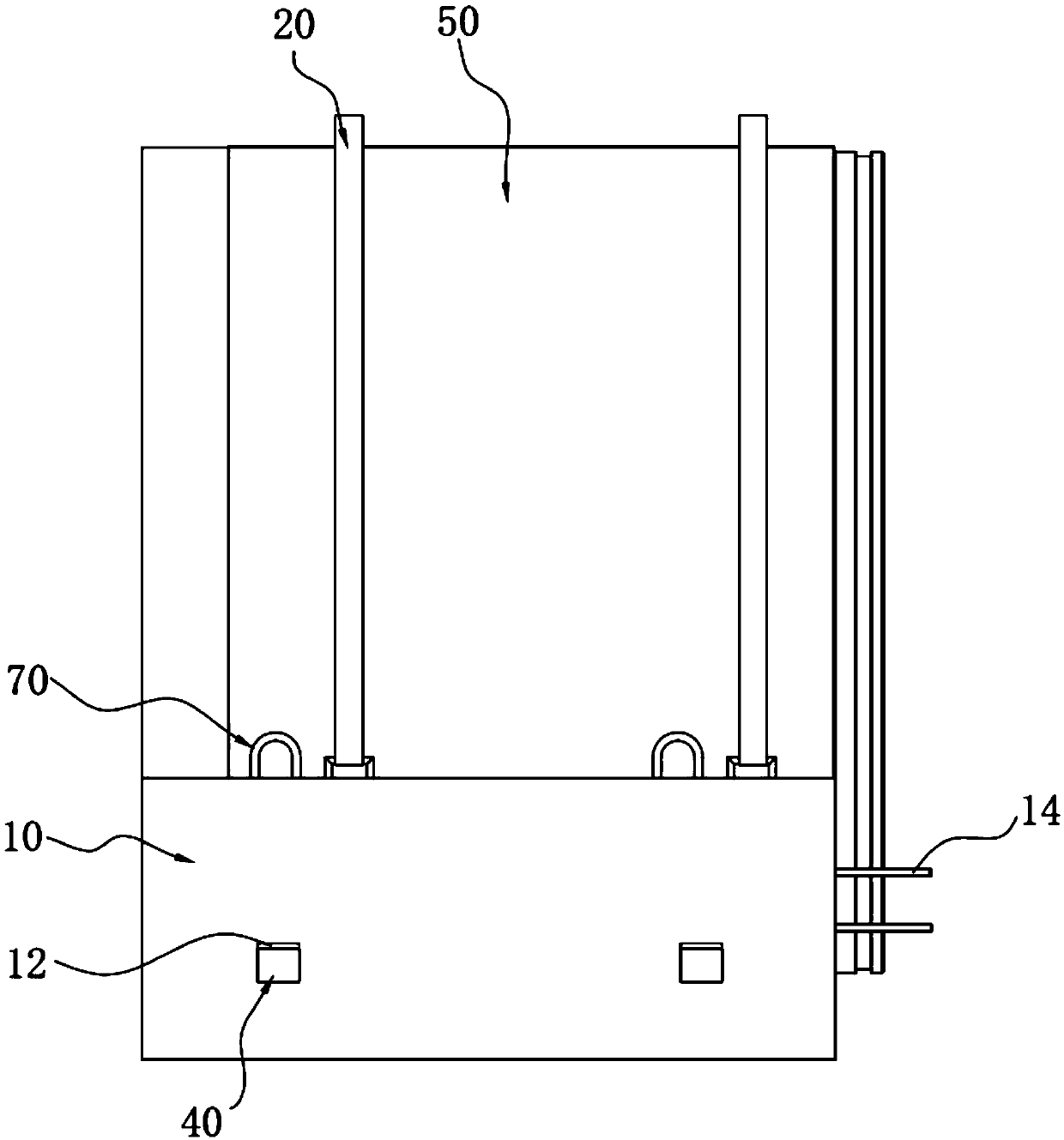
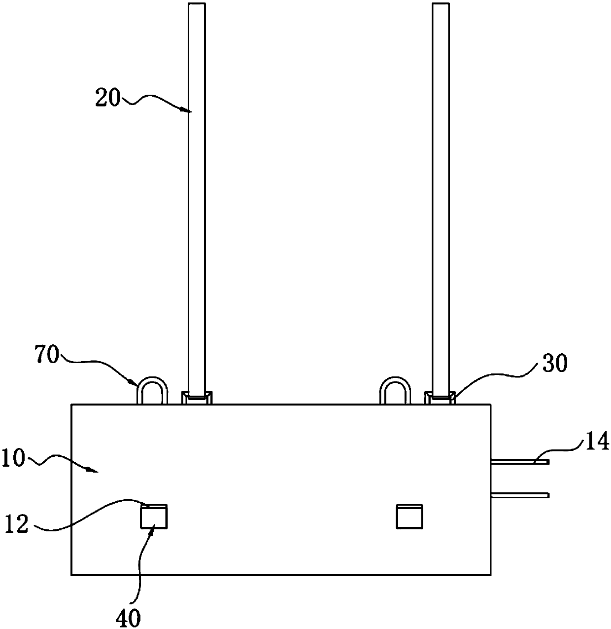
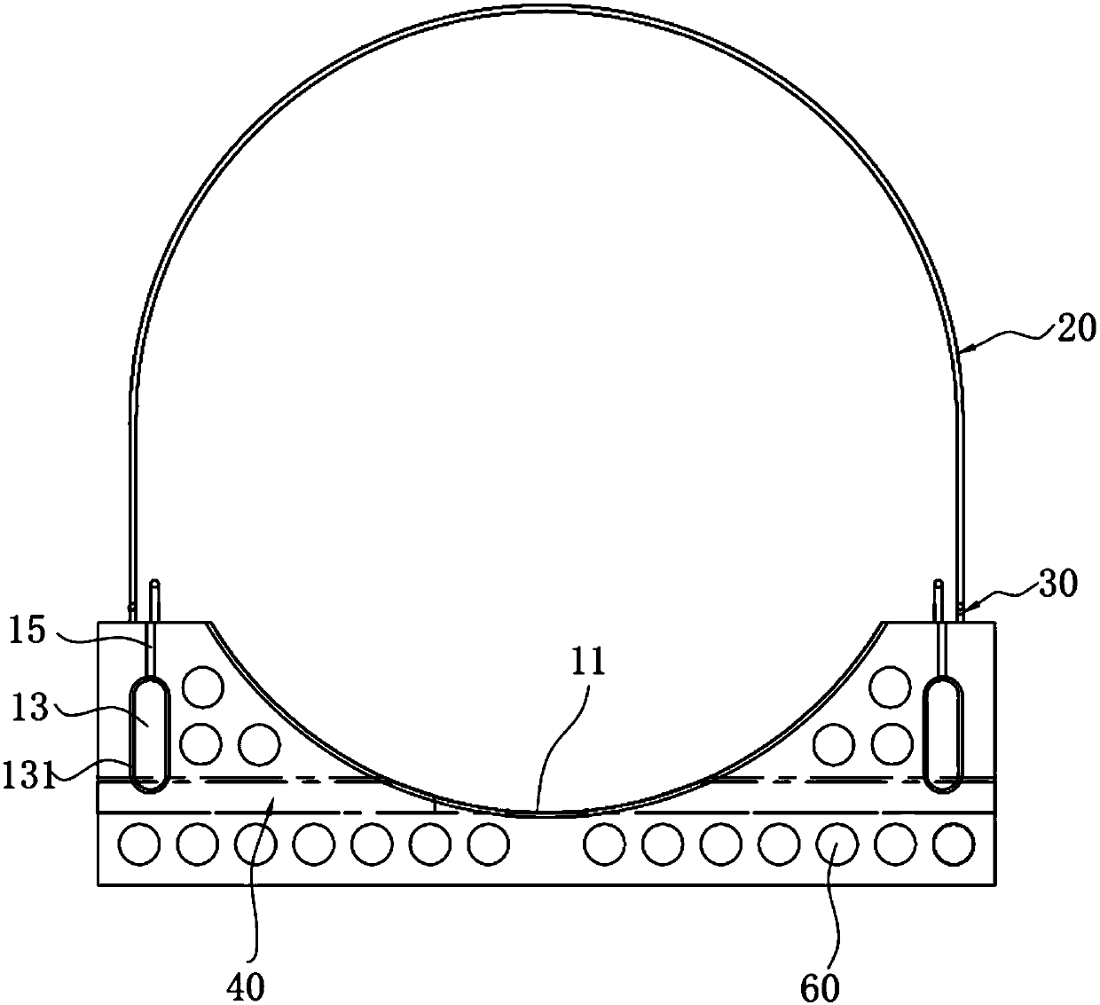
[0034] In the present invention, the structure of each pipe-based pipe joint unit is the same. In the embodiment, only for the convenience of illustration, the first installed pipe-based pipe joint unit is named the first pipe-based pipe joint unit, and the second installed pipe-based pipe joint unit is named as the first pipe-based pipe joint unit. The node unit is named as the second pipe-based pipe-section unit, and so on. Taking the first pipe-base pipe-section unit as an example, the structure of the pipe-base pipe-section unit is described in detail. Such as figure 1 As shown, the first pipe base pipe section unit includes the first pipe base 10, the first pipe section 50 and the fastening belt 20; as Figure 2 to Figure 4 As shown, the first tube base 10 is formed wit...


PUM


Abstract

The invention discloses a pipeline installing method. The pipeline installing method comprises the steps that a fastening belt is adopted for achieving temporary fastening of a first pipe base and a first pipe joint, and a first pipe base and pipe joint unit is formed; the first pipe base and pipe joint unit is hoisted into a base groove; the pipe inner bottom elevation of the first pipe joint inthe base groove is measured; gaps on the two sides between the first pipe joint and the first pipe base are closed; the preparing work for second pipe base and pipe joint unit installation is conducted; a second inserting port of a second pipe joint is inserted in a first port of the first pipe joint; the bell mouth end elevation of the position of a second bell mouth of the second pipe joint in the base groove is measured; a gap on the second bell mouth side between the second pipe joint and the second pipe base is closed; the steps from the fifth step to the eighth step are repeatedly conducted, and subsequent pipe base and pipe joint unit installation is finished; and cement mortar is poured into the positions between the pipe joints and the pipe bases in the same pipe base and pipe joint units and between the pipe bases between the adjacent pipe base and pipe joint units. According to the pipeline installing method, the hoisting frequency can be effectively reduced, and the advantage that construction is safe and reliable is achieved.

Description

technical field [0001] The invention relates to the technical field of pipeline installation, in particular to a pipeline installation method. Background technique [0002] At present, there are two methods for the installation and construction of road pipelines: one is to use the cast-in-place pipe foundation and then install the pipeline; method on the tube base. Although the method of cast-in-place pipe foundation in method 1 can achieve the purpose of supporting the pipeline, there are still the following problems: the cast-in-place pipe foundation needs to support the formwork at the construction site, and the reinforced concrete also needs to arrange steel bars, which increases the workload on the construction site. Large, long construction period. In method 2, the method of installing the pipe foundation first and then installing the pipe increases the number of hoisting, the work efficiency is relatively low, and the pipe foundation is easy to be damaged during the...

Claims


Application Information

Patent Timeline
Patent Type & Authority Applications(China)
IPC IPC(8): F16L1/036F16L1/06F16L1/11
CPCF16L1/036F16L1/06F16L1/11
Inventor 皇甫风雷朱民杨定锦
Owner KUNSHAN YUTENG MUNICIPAL ENG
Why Eureka
Try Eureka