Cooker convenient to clean, easy to adjust and with energy gathering ring

A convenient cleaning and energy-gathering ring technology, applied in the field of stoves, can solve the problems of hindering the cleaning of the user's liquid storage plate, reducing the utilization rate of gas combustion, and difficulty in satisfying consumers, etc., achieving stable and reliable combustion, uniform firepower distribution, and easy disassembly Effect

Pending Publication Date: 2019-04-02
成都前锋电子有限责任公司
View PDF10 Cites 2 Cited by
  • Summary
  • Abstract
  • Description
  • Claims
  • Application Information

AI Technical Summary

Problems solved by technology

Existing stoves are equipped with a separate liquid pan, which is fixed on the burner, but the following problems currently exist in the use of the above liquid pan: After the liquid pan receives the soup and oil from the overflowing pot, due to Near the center of the liquid pan, there are fixing screws, ignition pins, sensor pins and other parts, which will hinder the user from cleaning the liquid pan filled with soup and oil
However, most of the existing pot supports are made of iron rings with a circular cross section as a support frame and a plurality of support feet on the top of the support frame. Due to the large gap between the pot and the pot support, a large amount of heat generated by gas combustion The loss is radiated outward from the gap between the pot and the pot support, which reduces the utilization rate of gas combustion. At the same time, it is easy to make the switch next to the pot support hot, which is inconvenient to use.
Some people also adopt the energy-gathering ring structure on the fire distributor, but because the energy-gathering ring is fixed on the fire distributor, the energy-gathering ring cannot be quickly disassembled according to different needs during use, so the usage is single, and it is difficult to meet the requirements of consumers

Method used


Image

  • Cooker convenient to clean, easy to adjust and with energy gathering ring
  • Cooker convenient to clean, easy to adjust and with energy gathering ring
  • Cooker convenient to clean, easy to adjust and with energy gathering ring

Examples


Embodiment Construction

[0057] In order to make the purpose, technical solution and advantages of the present invention clearer, the present invention will be further elaborated below in conjunction with the accompanying drawings. In describing the present invention, it should be understood that the terms "upper", "lower", "front", "rear", "left", "right", "top", "bottom", "inner", " The orientation or positional relationship indicated by "outside", etc. is based on the orientation or positional relationship shown in the drawings, and is only for the convenience of describing the present invention and simplifying the description, rather than indicating or implying that the referred device or element must have a specific orientation, so as to Specific orientation configurations and operations, therefore, are not to be construed as limitations on the invention.

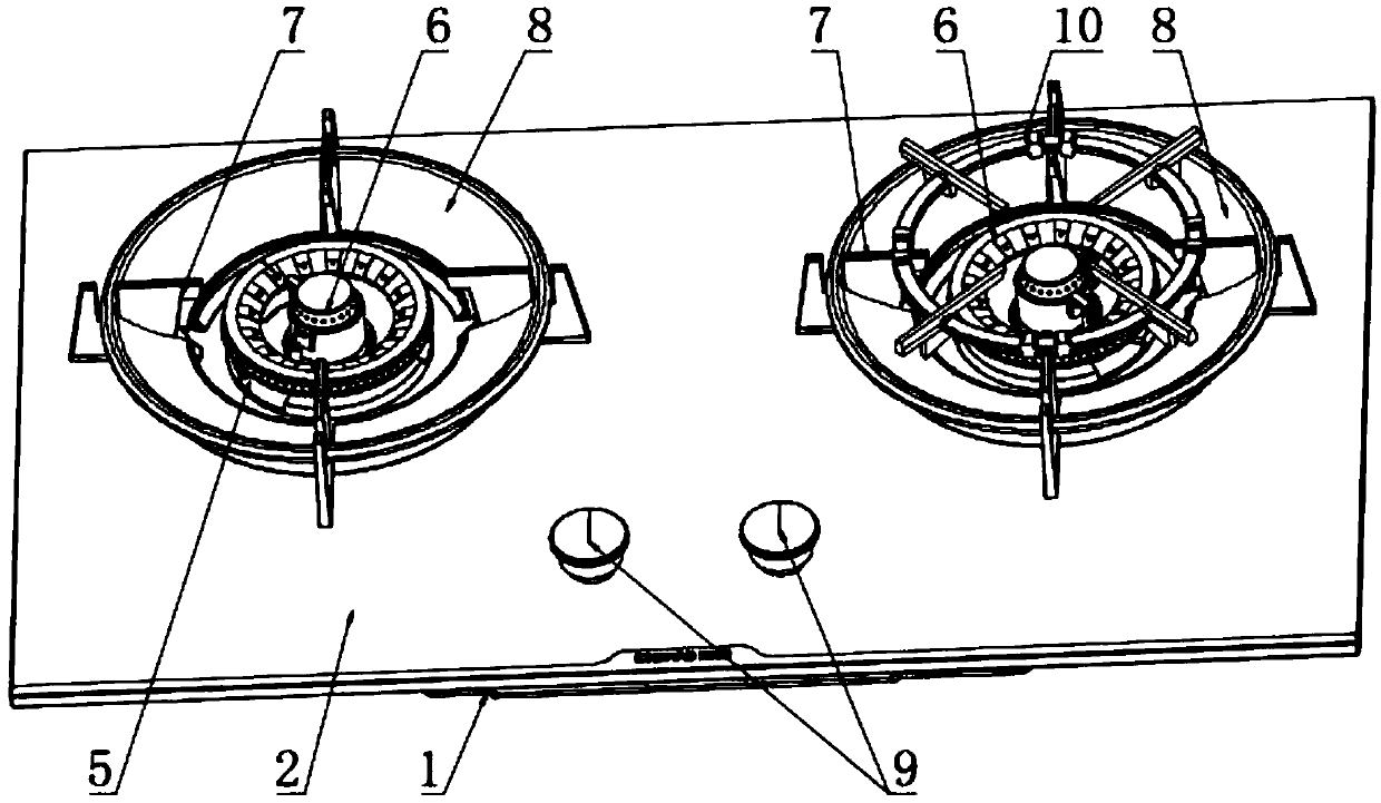
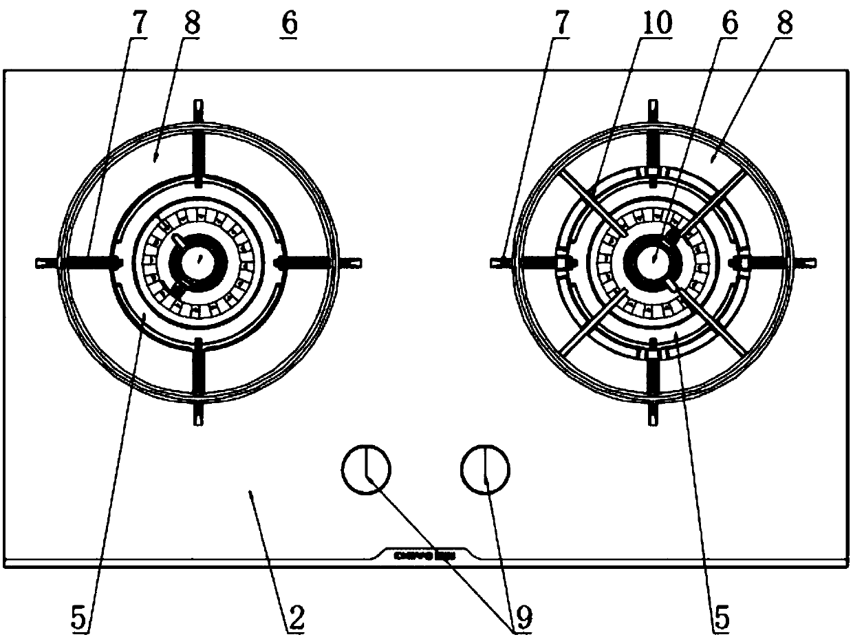
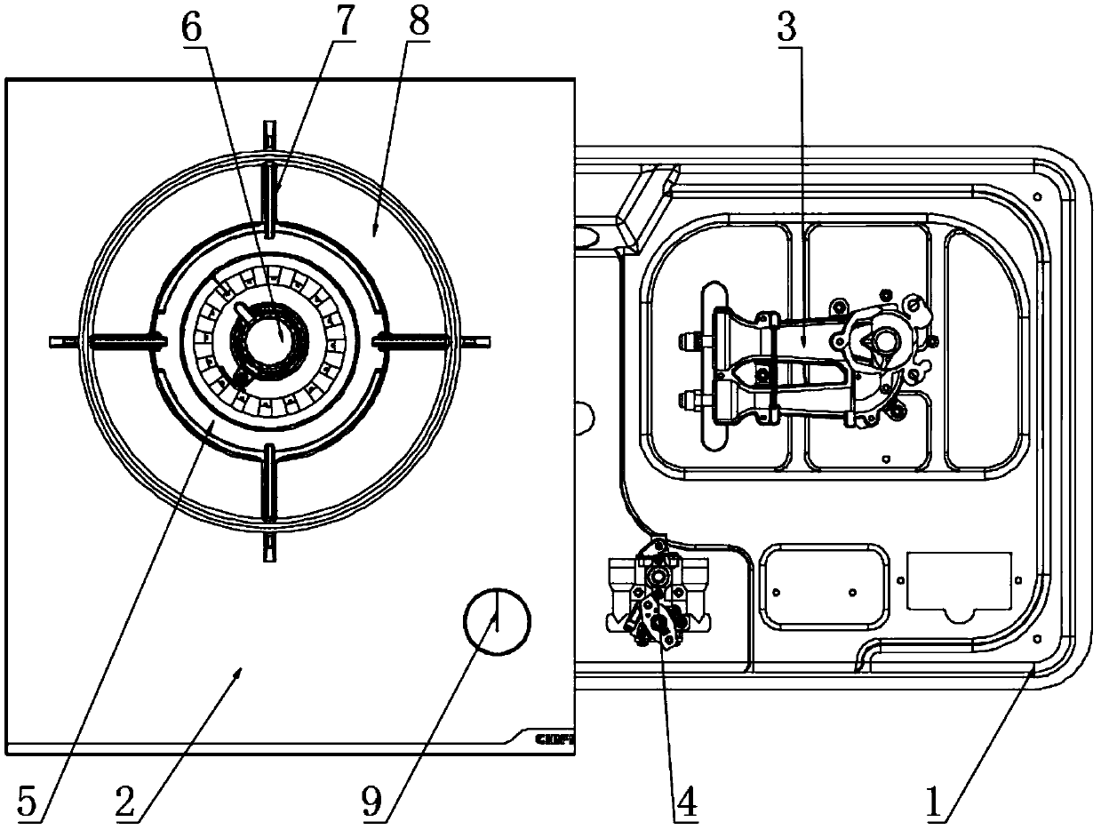
[0058] A stove that is easy to clean, easy to adjust and has an energy gathering ring, such as Figure 1-3 As shown, it includes a bottom ca...


PUM


Abstract

The invention discloses a cooker convenient to clean, easy to adjust and with an energy gathering ring. The cooker comprises a bottom shell, a panel, a burner, a valve body, a double-layer liquid holding disc, a fire distributor, a pan support I, the energy gathering ring and a knob. The double-layer liquid holding disc, the fire distributor, the pan support I and the energy gathering ring are allcoaxially arranged at the upper end of a burner hole I. The fire distributor is installed at a gas outlet of the burner and comprises an outer ring fire distributor and an inner ring fire distributor. The outer ring fire distributor is provided with an inner side burning hole and an outer side burning hole. Work of the cooker is controlled by the traditional mechanical knob, needs of many consumers can be met, and operation and cleaning are more convenient through the mechanical knob especially for middle and old age consumers often using mechanical knobs. Through the double-layer liquid holding disc, soup, oil dirt and other liquids are prevented from flowing into the inner space of the cooker and from influencing normal use of the cooker. The energy gathering ring is convenient to install and detach, heat loss generated after gas burning can be reduced effectively, and the heat utilization rate is increased.

Description

technical field [0001] The invention relates to a cooker, in particular to a cooker which is convenient to clean and easy to adjust and has an energy gathering ring, and belongs to the field of cooker. Background technique [0002] Gas cooker is the kitchen utensil commonly used in people's daily life, is a kind of cooker that mainly burns with combustible gas as fuel. The combustible gas can be natural gas, liquefied petroleum gas, artificial gas, etc. According to the different types of combustible gas, gas stoves can be divided into many types, such as liquefied gas stoves, artificial gas stoves, natural gas stoves, etc.; It is divided into single stove, double stove, single-eye stove, multi-eye stove, desktop embedded stove, etc. [0003] The liquid pan is an important part of the gas cooker. Its function is to centrally collect the overflowing soup for easy cleaning, and at the same time prevent the soup from flowing into the cooker and affect the normal use of the coo...

Claims


Application Information

Patent Timeline
Patent Type & Authority Applications(China)
IPC IPC(8): F24C3/08F24C3/12F24C15/10F24C15/14
CPCF24C3/085F24C3/126F24C15/10F24C15/14
Inventor 纪旭艾磊
Owner 成都前锋电子有限责任公司
Why Eureka
Try Eureka