Bistatic forward-looking SAR imaging method in subduction mode

An imaging method and bistatic technology, applied in the direction of instruments, measuring devices, and using re-radiation, can solve the problems of limited application, complex and limited bistatic trajectory, etc.

Active Publication Date: 2019-04-02
江苏天域航空科技集团股份有限公司
View PDF2 Cites 5 Cited by
  • Summary
  • Abstract
  • Description
  • Claims
  • Application Information

AI Technical Summary

Problems solved by technology

[0005] Compared with the traditional level-flying bistatic SAR, the height of the missile changes with time when the missile-borne SAR dives, and the bistatic trajectory is more complicated, which limits the application of the conventional bistatic forward-looking SAR imaging method.
Most of the existing studies on the subduction and descent of missile-borne SAR are researches on the subduction imaging of single-base missile-borne SAR, and due to the institutional limitations of single-base SAR, the research is limited to side-view and squint imaging of missile-borne SAR dive. method

Method used


Image

  • Bistatic forward-looking SAR imaging method in subduction mode
  • Bistatic forward-looking SAR imaging method in subduction mode
  • Bistatic forward-looking SAR imaging method in subduction mode

Examples


Embodiment Construction

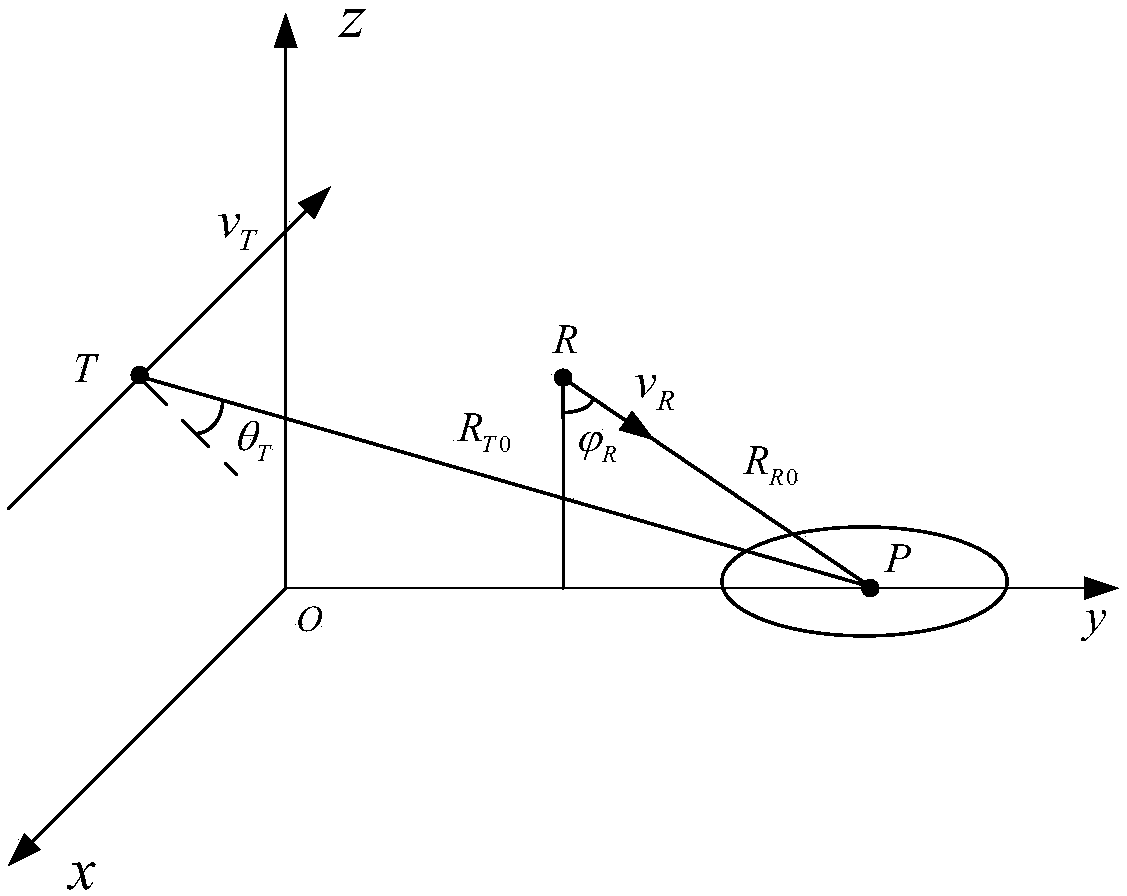
[0026] For the geometric model of the bistatic forward-looking SAR with constant speed subduction, the slant range history of the system at time t can be expressed as:

[0027]

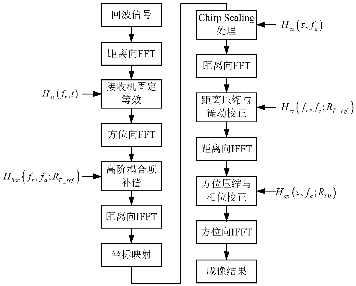
[0028] It can be seen from formula (1) that when the missile dives and descends at a constant speed, it moves toward the target, and the receiver moves in a straight line at a constant speed relative to the target, which brings a linear walking term and a fixed distance term in the bistatic slant range history. In the imaging processing of this paper, the linear term is firstly compensated in the range frequency domain-azimuth time domain, and converted into the echo signal of the transmitter squint and the receiver fixed mode, and then the mature monostatic SAR imaging method is used to carry out deal with.

[0029] Neglecting the non-backscattering coefficient of the ground target point, the expression of the echo signal received by the missile when diving at a constant speed is

[0030]

[0...


PUM


Abstract

The invention discloses a bistatic forward-looking SAR imaging method in a subduction mode. The method comprises the steps: proposing an imaging model in which a reconnaissance plane cooperates with amissile, the track is vertical, and the missile performs a uniform diving attack; establishing a geometric model of an uniform diving bistatic forward-looking SAR; providing a model corresponding toslant range history; and proposing an imaging algorithm based on receiver fixed equivalent for characteristics of the slant range history. According to the method, the double missiles matching model adopts an action mechanism that a missile attack and a missile performs irradiation and imaging, and an irradiation missile is away from an imaging area.

Description

technical field [0001] The invention relates to a bistatic forward-looking SAR imaging method in a subduction mode, and mainly studies the subduction imaging guidance of a reconnaissance aircraft and a missile. To ensure safety, the reconnaissance aircraft irradiates outside the defense zone, and the missile flies to the target area to obtain echo signals and image them. The reconnaissance plane is perpendicular to the trajectory of the missile, and the missile dives to attack the target area, and the corresponding imaging algorithm is designed. Background technique [0002] The key to realizing intelligent strike and precise strike is to improve the detection, identification and resolution capabilities of the terminal guidance section of precision-guided weapons. The terminal guidance radar of active anti-ship missiles mainly obtains the angle and distance information of the target through single-pulse angle measurement or one-dimensional range image. Meet the increasing t...

Claims


Application Information

Patent Timeline
Patent Type & Authority Applications(China)
IPC IPC(8): G01S13/90
Inventor 章晨光管建伟
Owner 江苏天域航空科技集团股份有限公司
Why Eureka
Try Eureka