
Reinforcing base for box-type transformer station

A box-type substation and bottom plate technology, which is applied to the details of substation/switch layout, electrical components, and anti-seismic equipment, can solve the problems of box-type substations shaking and dumping, and the vibration amplitude is large. Strong connection

Inactive Publication Date: 2019-04-02
吴杰军
View PDF0 Cites 1 Cited by
  • Summary
  • Abstract
  • Description
  • Claims
  • Application Information

AI Technical Summary

Problems solved by technology

[0004] The purpose of the present invention is to provide a reinforced base for a box-type substation, so as to solve the problem that the vibration amplitude is too large during shock absorption in the above-mentioned background technology, and it is easy to cause the box-type substation to shake and topple.

Method used


Image

  • Reinforcing base for box-type transformer station
  • Reinforcing base for box-type transformer station
  • Reinforcing base for box-type transformer station

Examples


Embodiment Construction

[0024] It should be understood that the specific embodiments described here are only used to explain the present invention, but not to limit the present invention.

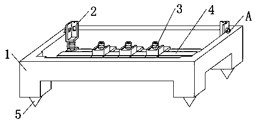
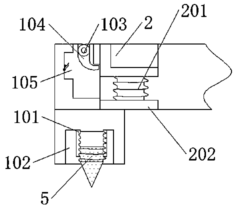
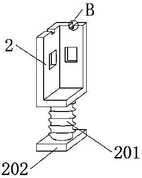
[0025] See figure 1 Attached Image 6 , A reinforced base for a box-type substation, including: the reinforced base for a box-type substation includes a frame 1, an adjusting fixed column 101, a support block 102, a rotating shaft 103, a buckle plate 104, a slide 105, a supporting card plate 2, a spring Block 201, bottom plate 202, sliding plate 203, connecting hole 204, bearing block 3, spring column 301, bearing plate 302, bearing column 4 and bottom cone 5. The bottom four corners of frame 1 are integrally provided with support blocks 102, and support blocks 102 The top of the middle part is welded with an adjusting and fixing column 101, and the middle of the bottom of the adjusting and fixing column 101 is screwed with a bottom cone 5. The bottom side of the left and right ends of the inner wall of the frame 1 a...


PUM


Abstract

The invention provides a reinforcing base for a box-type transformer station. Support block are integrally disposed on the four corners of the bottom of a frame. An adjustment fixing column is weldedto the middle top of each support block. The middle of the bottom of each adjustment fixing column is in threaded connection with a bottom cone. Bottom plates are welded to the bottom sides of the left and right ends at the rear side of the inner wall of the frame. Spring blocks are welded to the middles of the tops of the bottom plates. A support engagement plate is welded to the top of each spring block. A slide plate is welded to the middle of the outer side of each support engagement plate. A connecting hole is embedded in the middle of the top of each support engagement plate. Slideways are embedded in both the left and right sides of the frame. The middle part of the top of each slideway is movably connected with a swivel plate through a rotating shaft. A load-bearing column is welded to the bottom of the middle of the frame. A load-bearing block is welded to the top of the load-bearing column. A spring column is welded to the middle part of the top of the load-bearing block. A receiving plate is embedded in the middle of the top of the spring column. The reinforcing base of the invention has stable structure, a good drainage capacity, a good shock absorption effect, and canlimit the vibration amplitude, and is stable to use.

Description

Technical field [0001] The invention belongs to the technical field of substation support equipment, and in particular relates to a reinforced base for a box-type substation. Background technique [0002] Most of the box-type substations are located outdoors, and most of the box-type substations are located on the edge of the road, making the box-type substations easy to be touched by vehicles, which may cause the box-type substations to shake or tip over. At the same time, large vehicles such as trucks may cause road surfaces when they are driving. Vibration, which causes the box-type substation to shake. Most of the existing box-type substation bases use shock-absorbing springs. During the shock absorption process, the vibration of the shock-absorbing spring is too large, which makes the box-type substation follow the shock-absorbing spring. Jitter, when the jitter amplitude is too large, the box-type substation is easy to tilt, and when it is severe, it will tip over, seriousl...

Claims


Application Information

Patent Timeline
Patent Type & Authority Applications(China)
IPC IPC(8): H02B1/54H02B1/50
CPCH02B1/54H02B1/505
Inventor 吴杰军
Owner 吴杰军
Learn More