Hydraulic drive

A hydraulic and facility technology, applied in the direction of fluid pressure actuation devices, mechanical equipment, engine components, etc., can solve the problems of complexity, large flow loss, long flow path, etc., to achieve low flow loss, minimized heat input, high speed Effect

Active Publication Date: 2019-04-02
VOITH PATENT GMBH
View PDF11 Cites 0 Cited by
  • Summary
  • Abstract
  • Description
  • Claims
  • Application Information

AI Technical Summary

Problems solved by technology

[0003] Although in the mentioned hydraulic drive installations it is already possible to automatically switch between the fast stroke and the load stroke, this structure is due to the series connection of different switching valves through which the hydraulic fluid flows from the annular side or flows into the cylinder on the piston side) and the flow losses are relatively large due to the long set flow path of the liquid fluid

Method used


Image

  • Hydraulic drive
  • Hydraulic drive
  • Hydraulic drive

Examples


Embodiment Construction

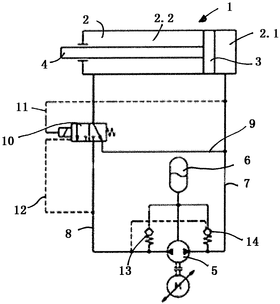
[0031] figure 1 An exemplary embodiment of a hydraulic drive according to the invention is shown in , which has a differential cylinder 1 with a cylinder piston 3 displaceably mounted in a cylinder chamber 2 . The cylinder piston 3 separates the cylinder chamber 2 into a piston side 2.1 and an annular side 2.2. On the piston side 2.1, a fully circular pressure surface acts on the cylinder piston 3, and on the annular side 2.2, an annular pressure surface acts on the cylinder piston 3 due to the piston rod 4 being connected to the cylinder piston 3.

[0032] A hydraulic pump 5 is provided, which is currently operable in two opposite directions of rotation, so that the hydraulic pump 5 can selectively supply hydraulic fluid from the hydraulic fluid reservoir 6 into each of the two hydraulic lines 7 and 8 , through the hydraulic line, the hydraulic pump 5 is connected to the differential cylinder 1 or its cylinder cavity 2 .

[0033] Via the first hydraulic line 7 hydraulic flu...


PUM


Abstract

The invention relates to a hydraulic drive having a differential cylinder (1), which has a cylinder piston (3) and a piston rod (4), which is connected to the cylinder piston (3), wherein the cylinderpiston (3) is arranged in a displaceable manner in a cylinder chamber (2) in order to extend and retract the piston rod (4), and the cylinder chamber (2) is separated by the cylinder piston (3) intoa piston side (2.1), on the one hand, and a ring side (2.2) with the piston rod (4), on the other hand, each with a variable volume; wherein the piston side (2.1) and the ring side (2.2) are separatedfrom one another by the piston (3) and are connected to one another in a fluid-conducting manner via a short-circuit line (9), and the short-circuit line (9) contains a switching valve (10) for optionally shutting off the short-circuit line (9) in a fluid-tight manner; having a hydraulic pump (5), which is connected to the differential cylinder (1) via hydraulic lines (7, 8), in order to delivera hydraulic fluid optionally to the piston side (2.1) or the ring side (2.2) and thus to displace the cylinder piston (3) in alternating fashion in the cylinder chamber (2); wherein the switching valve (10) can be switched into its blocking position at least indirectly in dependence on the pressure on the piston side (2.1) of the cylinder chamber (2); The invention is characterized in that the short-circuit line (9) contains a single switching valve (10), by means of which the short-circuit line (9) can be shut off.

Description

technical field [0001] The invention relates to a hydraulic drive, for example for hydraulic presses or other working machines or machine tools, wherein the hydraulic drive has a cylinder with a cylinder piston and a piston coupled to the cylinder piston on one side The rod is used to form a so-called differential cylinder, so that the displacement of the cylinder piston in the cylinder chamber and the resulting movement of the piston rod in and out can drive the pressing element or other elements. Background technique [0002] Such a hydraulic drive is known, for example, from DE 10 2014 016 296 A1, wherein the hydraulic drive shown in this document is capable of rapid strokes and load strokes. During the rapid stroke, hydraulic fluid is guided from the ring side along with the piston rod to the piston side of the differential cylinder in order thereby to enable the cylinder piston to move faster in the cylinder chamber. In the load stroke (in which a greater force of the ...

Claims


Application Information

Patent Timeline
Patent Type & Authority Applications(China)
IPC IPC(8): F15B7/00
CPCF15B7/006F15B2011/0243F15B2211/20515F15B2211/20561F15B2211/27F15B2211/3051F15B2211/7053F15B2211/775F01L1/46F04B1/0421F04B49/002
Inventor 芒努斯·朱津格
Owner VOITH PATENT GMBH
Why Eureka
Try Eureka