Compressed air heat energy recovery and control system

A technology of compressed air and control system, applied in pump control, liquid variable volume machinery, variable volume pump components, etc., can solve the lack of comprehensive control, inability to compress air regulation control, lack of safety and convenience of use, etc. problems, to achieve stable work, ensure automatic operation, and facilitate use and maintenance.

Active Publication Date: 2014-02-12
杭州山立净化设备股份有限公司
View PDF7 Cites 9 Cited by
  • Summary
  • Abstract
  • Description
  • Claims
  • Application Information

AI Technical Summary

Problems solved by technology

The disadvantage of this technical solution is that, firstly, the heat dissipation is adjusted only according to the cooling outlet temperature of the air compressor without considering the operating parameters such as the temperature and pressure of the compressed air itself, lack of comprehensive control, which is not conducive to the normal operation of

Method used


Image

  • Compressed air heat energy recovery and control system
  • Compressed air heat energy recovery and control system

Examples


Embodiment

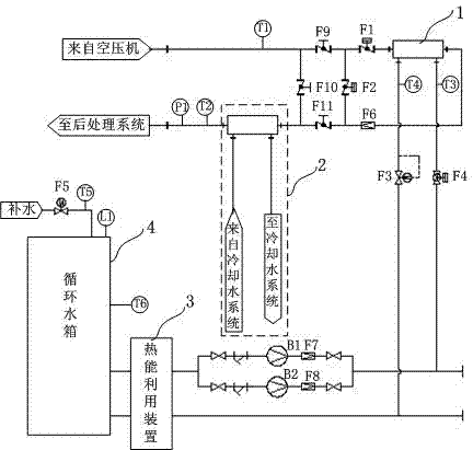
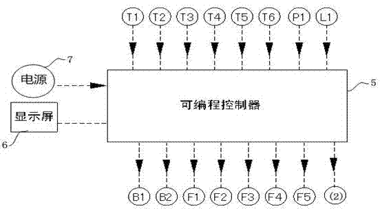
[0019] Example: as figure 1 , figure 2 As shown, the present invention is a compressed air heat recovery and control system. The compressed air output port of the air compressor is sequentially connected to the first manual valve F9, the intake pneumatic valve F1, the heat exchanger 1, the one-way valve F6, the third manual valve F11, the water cooling system 2 and the after-treatment system of the compressed air; The first manual valve F9 is installed between the air inlet of the air intake pneumatic valve F1 and the air outlet of the air compressor (compressed air output port), between the air inlet of the first manual valve F9 and the air inlet of the water cooling system 2 ( The second manual valve F10 is installed between the water-cooled compressed air inlet), and the third manual valve F11 is installed between the air outlet of the bypass pneumatic valve F2 and the air inlet of the water-cooling system 2; the circulating water inlet of the heat exchanger 1 is sequenti...


PUM


Abstract

The invention discloses a compressed air heat energy recovery and control system. The control valve opening of a circulating water exit is regulated according to parameters of pressure, temperature, liquid level and the like. The whole system can perform automatic operation and the use is convenient. The compressed air heat energy recovery and control system comprises a heat exchanger, a water cooling system, a heat energy utilization device, a circulation water tank with a water inlet pipe, a circulating pump and a controller, wherein a compressed air outlet of an air compressor is connected with the heat exchanger, the heat exchanger is further respectively connected with the circulating pump and the water cooling system, the circulating pump is connected with the circulation water tank through the heat energy utilization device, the controller is respectively connected with an air inlet temperature sensor, an air outlet temperature sensor, an air outlet pressure sensor, a circulating water inlet temperature sensor, a circulating water outlet temperature sensor, a circulating water tank water supply inlet temperature sensor, a circulating water tank temperature sensor, a liquid level sensor, an inlet pneumatic valve, a by-pass pneumatic valve, an electric valve, a control valve, a water supply magnetic valve, the circulating pump and the water cooling system.

Description

technical field [0001] The invention relates to an air compressor, in particular to a compressed air heat recovery device and a control system for the air compressor. Background technique [0002] With the rapid development of industrialization, the application of air compressors is becoming more and more extensive. At present, the power consumption of air compressors is estimated to account for about 25% of the total power grid, and even higher in some industries. The use efficiency of air compressors is generally low, and the proportion of electric energy actually consumed to increase the potential energy of the air is relatively small, and most of the electric energy is converted into heat and discharged through cooling. In fact, the recoverable heat of the air compressor accounts for 40%-90% of the input power, and the waste heat recovery of the air compressor is becoming more and more important. [0003] The patent document with the publication date of December 8, 2010...

Claims


Application Information

Patent Timeline
IPC IPC(8): F04B39/00F04B49/00
Inventor 洪川吴俊李铭
Owner 杭州山立净化设备股份有限公司
Why Eureka
Try Eureka