
Powder spreading device

A technology of powder spreading device and knife core, applied in the field of additive manufacturing, can solve the problems of poor powder spreading quality of powder spreading device, low utilization rate of scraper, impact of scraper on product performance, etc.

Inactive Publication Date: 2019-04-05
HANS LASER TECH IND GRP CO LTD +1
View PDF5 Cites 2 Cited by
  • Summary
  • Abstract
  • Description
  • Claims
  • Application Information

AI Technical Summary

Problems solved by technology

[0005] The main purpose of the present invention is to provide a powder spreading device, which aims to solve the technical problems of poor powder spreading quality, low scraper utilization rate, and frequent replacement of scrapers affecting product performance in the prior art

Method used


Image

  • Powder spreading device
  • Powder spreading device
  • Powder spreading device

Examples


Embodiment Construction

[0015] In order to make the purpose, features and advantages of the present invention more obvious and understandable, the technical solutions in the embodiments of the present invention will be clearly and completely described below in conjunction with the accompanying drawings in the embodiments of the present invention. Obviously, the described The embodiments are only some of the embodiments of the present invention, but not all of them. Based on the embodiments of the present invention, all other embodiments obtained by those skilled in the art without making creative efforts belong to the protection scope of the present invention.

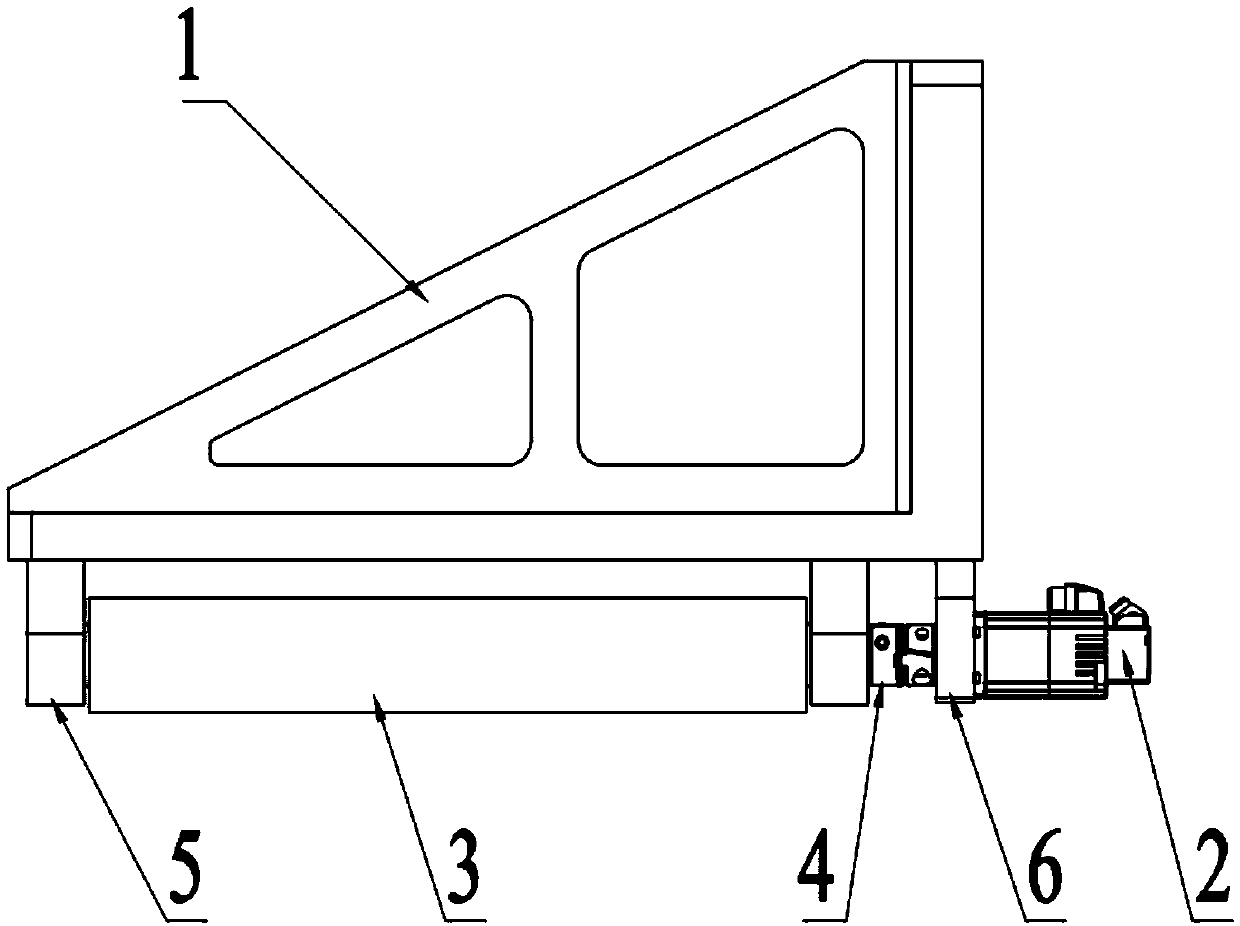
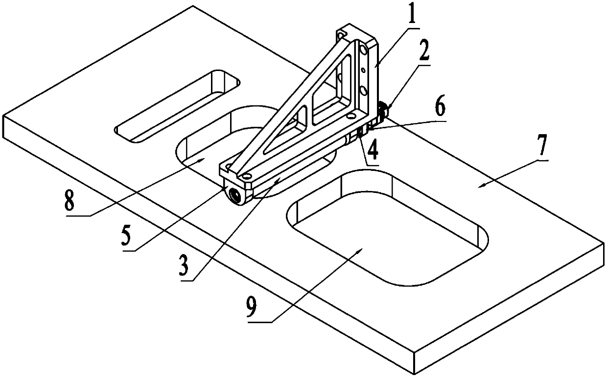
[0016] see figure 1 , figure 1 It is a schematic structural diagram of a powder spreading device provided by an embodiment of the present invention.

[0017] Depend on figure 1 As can be seen, the powder spreading device comprises:

[0018] Scraper holder 1, drive motor 2, flexible scraper 3 and coupling 4.

[0019] Further, the flexible...


PUM


Abstract

The invention discloses a powder spreading device, and relates to the technical field of additive manufacturing. The powder spreading device comprises a scraper frame, a drive motor, a flexible scraper and a coupler. The flexible scraper comprises a scraper core and a scraper sleeve; the scraper core is of a cylinder structure; the scraper sleeve is of a hollow cylinder structure; the scraper coreis sleeved with the scraper sleeve; the flexible scraper and the drive motor are installed on the scraper frame; and a rotary shaft of the drive motor is connected with one end of the flexible scraper through the coupler. The drive motor is connected with the flexible scraper. after the part of the flexible scraper is abraded, the drive motor can drive the flexible scraper to be rotated by any angle, the contact position of the flexible scraper and powder is adjusted again, the part, not abraded, of the flexible scraper makes contact with the powder, the flexible scraper can be continue to beused, the utilization rate of the scraper is improved, the drive motor controls the position of the scraper, a cabin door does not need to be opened, formed parts are not oxidized, and the printing quality is ensured.

Description

technical field [0001] The invention relates to the technical field of additive manufacturing, in particular to a powder spreading device. Background technique [0002] Metal laser 3D printing technology is also called additive manufacturing and rapid prototyping technology. Metal parts formed by metal laser 3D printing have the advantages of high density, high strength and low surface roughness, and can reduce the initial investment of personalized complex parts Cost and save manufacturing time, so it is widely used in automotive, aerospace, marine, jewelry, medical and other fields. [0003] The forming principle of metal laser 3D printing technology is to use 3D data as a template, first spread a layer of metal powder evenly on the forming substrate, use the high-energy laser beam to melt the metal powder according to the slicing data of the forming part, and then spread it on the forming substrate. A layer of metal powder, and then melt the metal powder according to the...

Claims


Application Information

Patent Timeline
IPC IPC(8): B22F3/105B33Y30/00
CPCB33Y30/00B22F10/00B22F12/63B22F10/28B22F12/226Y02P10/25
Inventor 许建波刘鹏宇张海东董银龙雨刘旭飞陈根余陈焱高云峰
Owner HANS LASER TECH IND GRP CO LTD
Learn More