Method for improving debugging precision of laser marking system

A technology of laser marking and high-precision processing, applied in laser welding equipment, welding equipment, metal processing equipment, etc., can solve the problems of low accuracy of collected images and uneven processing, so as to improve the effect and efficiency, and improve the consistent processing effect. , the effect of reducing negative effects

Inactive Publication Date: 2019-04-05
HANS LASER TECH IND GRP CO LTD
View PDF11 Cites 5 Cited by
  • Summary
  • Abstract
  • Description
  • Claims
  • Application Information

AI Technical Summary

Problems solved by technology

[0007] The technical problem to be solved by the present invention is to provide a method for improving the debugging accuracy of the laser marking system in view of the above-mentioned defects of the prior art, aiming at solving the defects of low image acquisition accuracy and uneven processing in the existing laser processing

Method used


Image

  • Method for improving debugging precision of laser marking system
  • Method for improving debugging precision of laser marking system

Examples


Embodiment Construction

[0023] Now in conjunction with the accompanying drawings, the preferred embodiments of the present invention will be described in detail.

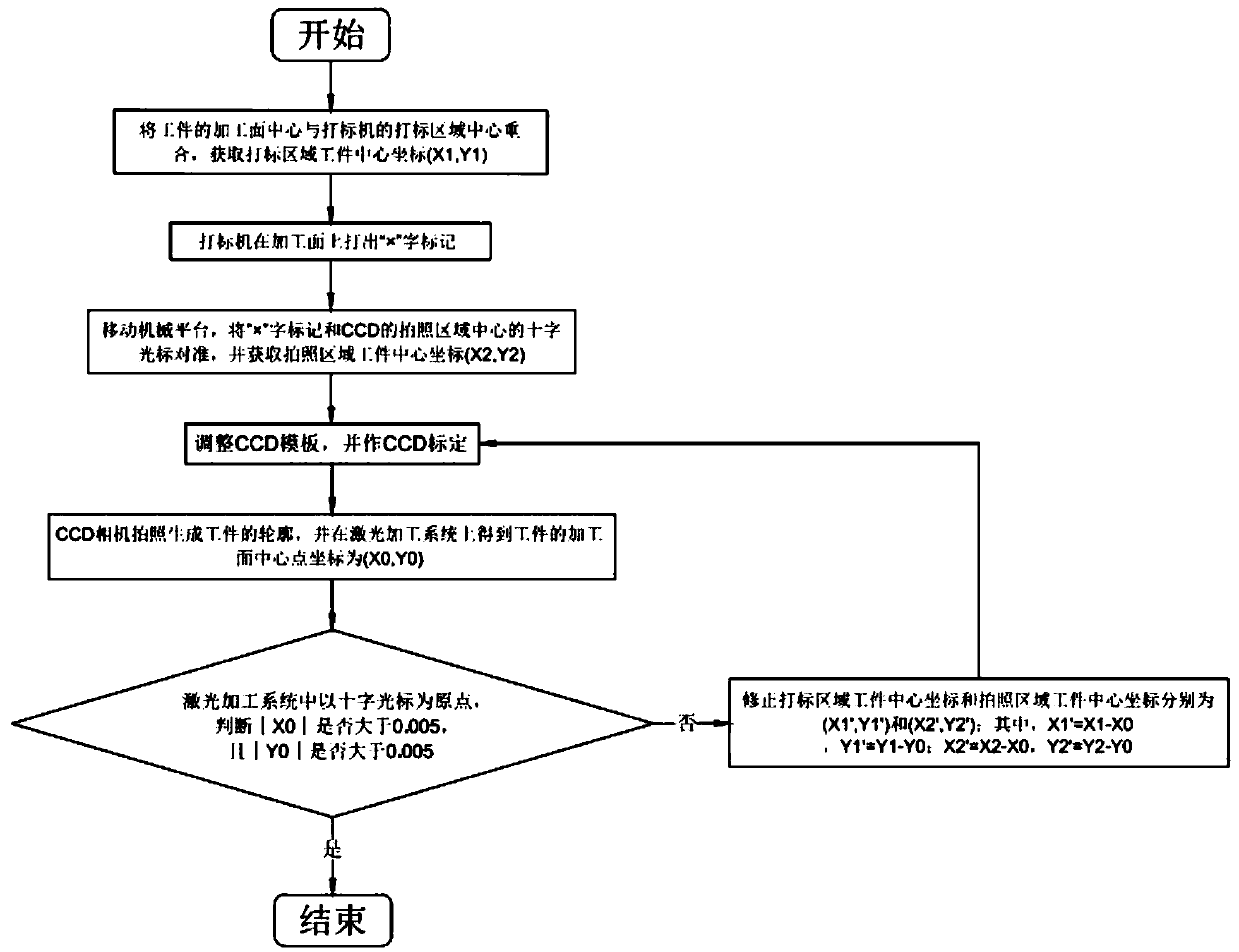
[0024] Such as figure 1 As shown, a method for improving the debugging accuracy of a laser marking system in this embodiment is used for laser marking equipment that requires large-format high-precision processing, and specifically includes the following steps:

[0025] Step 1. Coincide the center of the machining surface of the workpiece with the center of the marking area of ​​the marking machine to obtain the coordinates of the workpiece center in the marking area (X 1 ,Y 1 );

[0026] Step 2. The marking machine marks the word "×" on the processing surface;

[0027] Step 3. Move the mechanical platform, align the "×" mark with the cross cursor in the center of the photographing area of ​​the CCD, and obtain the coordinates of the workpiece center in the photographing area (X 2 ,Y 2 );

[0028] Step 4. Adjust the CCD template and ...


PUM


Abstract

The invention relates to the field of laser processing, in particular to a method for improving the debugging precision of a laser marking system. The method for improving the debugging precision of the laser marking system is used for laser marking equipment needing for large-format high-precision processing. The method for improving the debugging precision of the laser marking system comprises the steps that the processing surface center is coincident with a marking area center, an x mark is coincident with a cross cursor of the CCD photographed area center, and coarse standardization of a marking area workpiece center coordinate and a photographed area workpiece center coordinate; and then, a center point coincident of the coarse standardization and a cross cursor original point in a laser processing system are judged and fed back to be optimized back and forth, so that a processing surface center point is located at a center point of laser processing and image collecting, the situation of improving the processing effect of the edge position of a workpiece being consistent with the center position is facilitated, reduction of negative effects of lens distortion on processing precision is further facilitated, the precision of CCD collected images is improved, careful debugging of engineers does not depended on, and the debugging effect and efficiency are improved.

Description

technical field [0001] The invention relates to the field of laser processing, in particular to a method for improving the debugging accuracy of a laser marking system. Background technique [0002] In the laser precision machining system, the CCD-based positioning method is more flexible and more accurate than the traditional method of simply using mechanical positioning. At present, the general debugging scheme of the laser precision machining system based on CCD positioning is to find the marking point of the laser and the photographing point of the CCD, adjust the CCD template, and then start the test compensation and production after a successful calibration. point to adjust. [0003] This debugging method can meet the positioning accuracy requirements of ordinary CCDs, but for large-format high-precision laser precision machining systems, it has the following shortcomings: [0004] 1. Large-format and high-precision photography generally requires a large and fine CCD...

Claims


Application Information

Patent Timeline
Patent Type & Authority Applications(China)
IPC IPC(8): B23K26/03B23K26/362
CPCB23K26/032B23K26/362
Inventor 陈瑶胡述旭鲁力伟曹洪涛吕启涛高云峰
Owner HANS LASER TECH IND GRP CO LTD
Why Eureka
Try Eureka