Mixed resin defoaming device for wind power blade

A technology of mixing resin and wind power blades, applied in the field of resin defoaming molding, can solve the problems of long defoaming time, increasing production cost, sticking to the top of defoaming tank, etc.

Active Publication Date: 2019-04-05
LUOYANG SUNRUI WIND TURBINE BLADE
View PDF6 Cites 7 Cited by
  • Summary
  • Abstract
  • Description
  • Claims
  • Application Information

AI Technical Summary

Problems solved by technology

[0003] At present, the basic way of mixing and defoaming is to put the two-component resin into the defoaming box, and then transfer it to the infusion area after vacuum defoaming. Carry out above-mentioned operation repeatedly, the process is more loaded down with trivial details, has increased production cost
[0004] In the prior art, the rotating mechanism is generally used to rotate and defoam the resin entering the defoaming tank, and the defoaming time is long. Due to the characteristics of the resin itself, when the resin mixing and defoaming time is long, the resin starts to solidify and the temperature rises. It cannot be used; and the degassing tank will have a lot of bubbles overflowing during the degassing process, and the height of the bubbles will gradually increase as the degassing process progresses, and eventually stick to the top of the degassing tank, which is not easy to clean

Method used


Image

  • Mixed resin defoaming device for wind power blade
  • Mixed resin defoaming device for wind power blade
  • Mixed resin defoaming device for wind power blade

Examples


Embodiment Construction

[0036] The core of the present invention is to provide a mixed resin degassing device for wind power blades, which can effectively and quickly degas the resin, prevent the resin from overflowing, and have a better degassing effect.

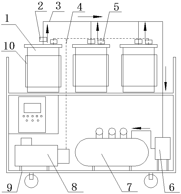
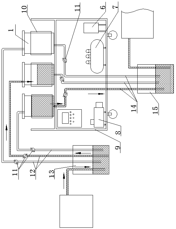
[0037] Please refer to Figure 1-2 , figure 1 It is a schematic diagram of the air extraction or air intake process of the degassing device provided by the present invention, figure 2 It is a schematic diagram of the feeding or discharging process of the degassing device in the present invention. The two figures combine to illustrate the working process of the degassing device as a whole.

[0038] A mixed resin defoaming device for wind power blades, comprising a double-layer operating platform 9, a plurality of defoaming tanks 1 placed on the upper layer of the double-layer operating platform 9, placed on the lower layer of the double-layer operating platform 9 and respectively connected to the defoaming tanks 1 The vacuum pumping part, the f...


PUM


Abstract

The invention discloses a mixed resin defoaming device for a wind power blade, and belongs to the field of resin defoaming and forming. The mixed resin defoaming device comprises a double-layer operating platform, a defoaming tank, a vacuumizing component, a feed component, a discharge component and an air inlet component, wherein the defoaming tank is arranged on the upper layer of the double-layer operating platform, the vacuumizing component, the feed component, the discharge component and the air inlet component are arranged on the lower layer of the double-layer operating platform, the vacuumizing component is connected with the defoaming tank through a pipeline so as to vacuumize the defoaming tank, the feed component is connected with the defoaming tank through a pipeline so as to convey resin to the vacuum defoaming tank, the discharge component is connected with the bottom of the defoaming tank through a pipeline so as to discharge defoamed resin, and the air inlet component is connected with the defoaming tank through a pipeline so as to increase the resin discharge speed; a disperser which communicates with a feed opening located in a top cover body of the defoaming tankthrough a pipeline and is used for spraying resin to the inner wall of the defoaming tank is arranged in the defoaming tank; and an anti-overflow component comprises a motor which is fixed to the cover body and a defoaming paddle which is in driving connection with the motor and extends into the defoaming tank. According to the defoaming device, continuous defoaming can be realized, the defoamingtime is short, the defoaming effect is good, and the resin can be prevented from overflowing.

Description

technical field [0001] The invention relates to the field of resin defoaming molding, in particular to a mixed resin defoaming device for wind turbine blades. Background technique [0002] Wind turbine blades are an important component of wind turbines, and their product quality directly affects the operation and power generation efficiency of wind turbines. The manufacturing process of large wind turbine blades is basically vacuum-assisted infusion molding (VARI). In order to improve the quality of infusion, the resin needs to be defoamed. Treatment, the commonly used deaeration process is divided into single-component deaeration and mixed deaeration. Due to its ready-to-use characteristics, mixed deaeration reduces the risk of re-introducing air bubbles after resin deaeration. Compared with single-component deaeration infusion Better results. [0003] At present, the basic way of mixing and defoaming is to put the two-component resin into the defoaming box, and then trans...

Claims


Application Information

Patent Timeline
Patent Type & Authority Applications(China)
IPC IPC(8): B29C39/24B29C39/42B29C39/44B29C39/22B29L31/08
CPCB29C39/22B29C39/24B29C39/42B29C39/44B29L2031/082Y02E10/72
Inventor 张育伟陈佳佳李雪原冯威王锋王磊赵辉
Owner LUOYANG SUNRUI WIND TURBINE BLADE
Why Eureka
Try Eureka