Ultrasonic wave demisting water removal lens

An ultrasonic and lens technology, applied in vehicle cleaning, vehicle maintenance, transportation and packaging, etc., can solve the problems of reducing water removal effect, huge kinetic energy loss, energy dispersion, etc.

Pending Publication Date: 2019-04-05
温州市华晖汽摩配件厂(普通合伙)
View PDF21 Cites 0 Cited by
  • Summary
  • Abstract
  • Description
  • Claims
  • Application Information

AI Technical Summary

Problems solved by technology

[0003] In response to the above problems, Chinese Patent No. 201220687863.7 discloses a patent for an ultrasonic automobile rearview mirror rain removal device, and proposes a scheme for removing water mist on the mirror surface using ultrasonic waves; however, its ultrasonic transducer is installed behind the mirror surface and is directly fixed to the mirror surface , according to this scheme, the vibration energy of the transducer is directly transmitted to the mirror surface, that is, the transducer directly causes the mirror surface to vibrate at high frequency; due to the large mass of the mirror surface and the small power of the transducer, it is difficult to drive the mirror surface to vibrate reliably , and even if it vibrates, the kinetic energy loss of the mirror is huge during the high-frequency back-and-forth movement; on the other hand, when the mirror vibrates, it pushes fluctuations to an area equal to the mirror surface, which makes the energy extremely dispersed and further reduces the water removal effect , the main principle is to achieve water removal through ultrasonic atomization

Method used


Image

  • Ultrasonic wave demisting water removal lens
  • Ultrasonic wave demisting water removal lens
  • Ultrasonic wave demisting water removal lens

Examples


Embodiment Construction

[0033] The specific implementation manners of the present invention will be further described in detail below in conjunction with the accompanying drawings and embodiments. The following examples are used to illustrate the present invention, but are not intended to limit the scope of the present invention.

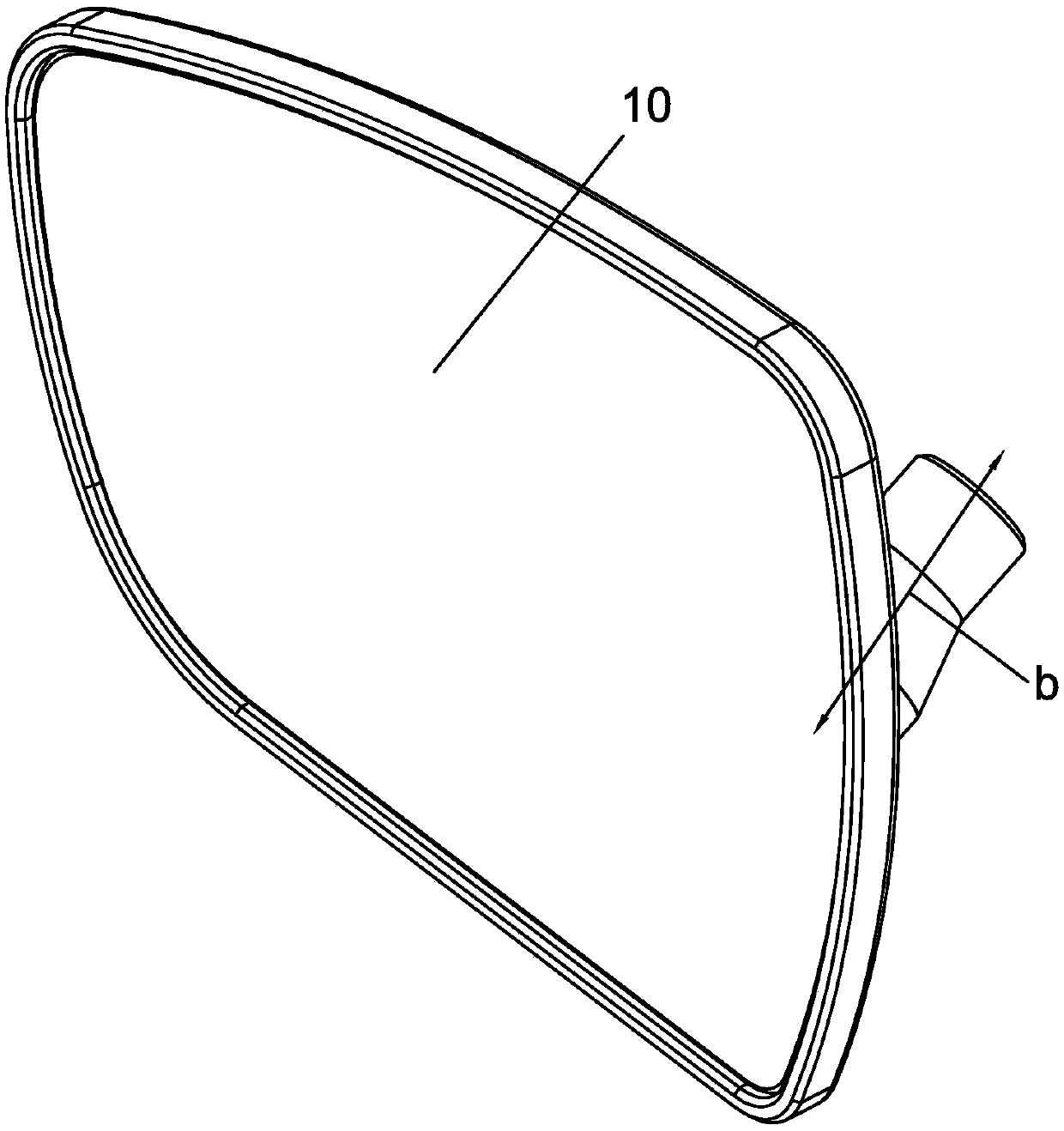
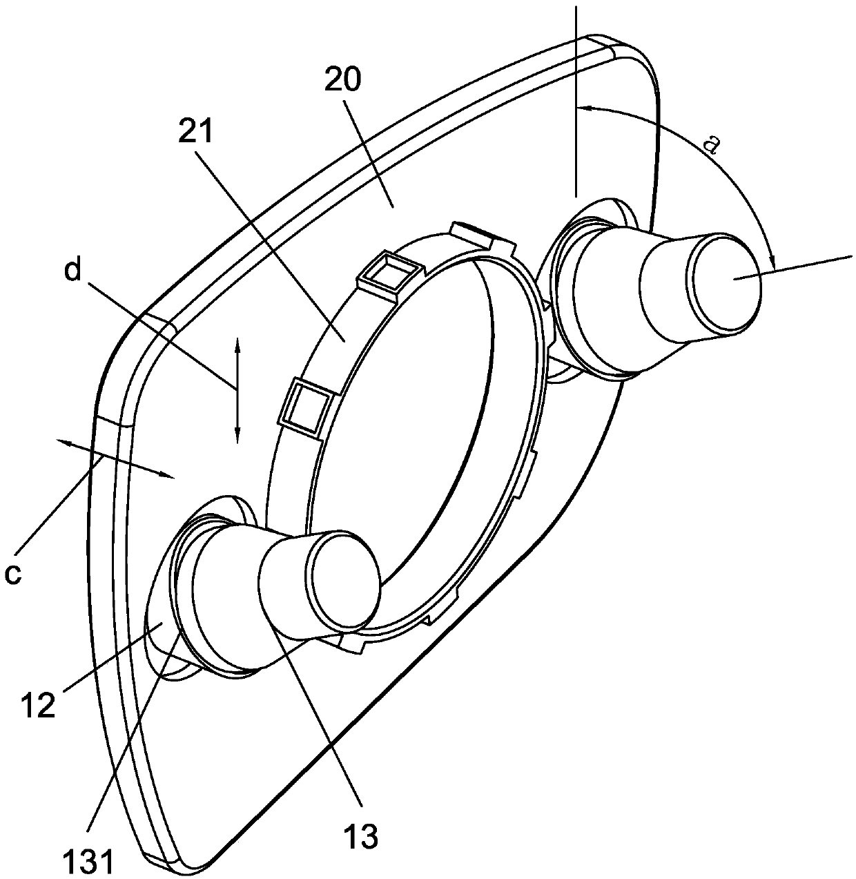
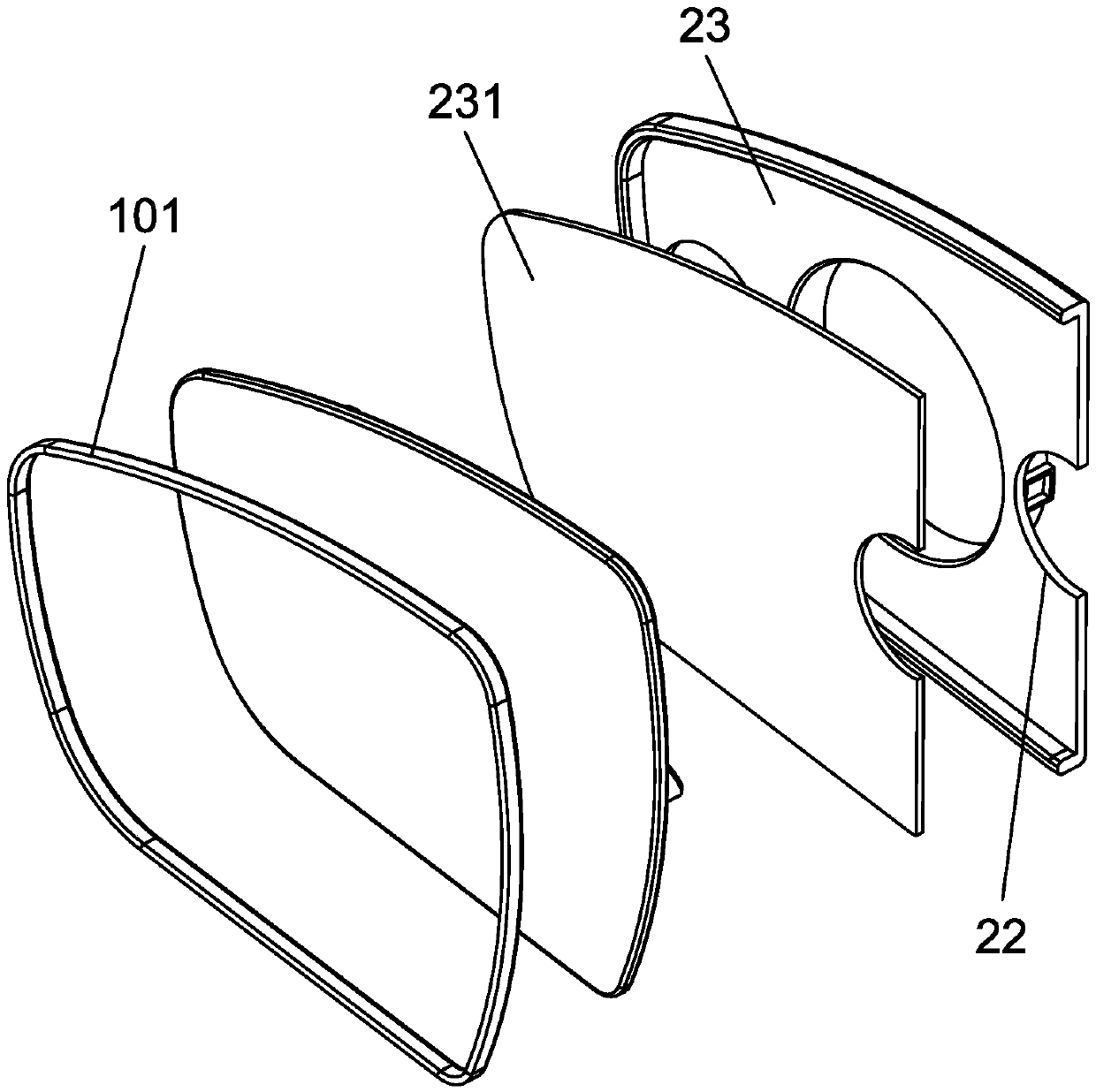
[0034] refer to Figure 1 to Figure 8 ,Such as Figure 1 to Figure 8 The shown ultrasonic defogging and water-repelling lens includes a lens glass 10 and a mounting frame 20, the back of the lens glass 10 is coated with a reflective layer 11, the lens glass 10 is installed on the mounting frame 20, and the mounting frame 20 Through the installation notch 21, it is fixed on the angle of view adjustment device (not shown in the figure) in the rearview mirror housing (not shown in the figure), and the periphery of the installation notch 21 of the installation frame 20 is provided with several through holes 22 The back of the lens glass 10 is provided with a number of ultras...


PUM


Abstract

The invention provides an ultrasonic wave demisting water removal lens which comprises lens glass and an installation frame. The back face of the lens glass is plated with a reflective layer. The lensglass is installed on the installation frame. The installation frame is fixed to a view angle adjusting device in a rearview mirror shell through an installation notch. Multiple through holes are formed in the periphery of the installation notch of the installation frame. The back face of the lens glass is provided with multiple ultrasonic seats arranged corresponding to the through holes. The ultrasonic seats penetrate through the through holes into the rearview mirror shell. The ultrasonic seats are provided with ultrasonic wave vibrators. The fixed ends of the ultrasonic wave vibrators face the lens glass and incline downwards to be connected with the ultrasonic seats. The included angle between the central axis of each ultrasonic wave vibrator and the vertical direction of the lens glass ranges from 30 degrees to 90 degrees. The ultrasonic wave demisting water removal lens has the advantages of being quick in water removal effect and good in demisting effect.

Description

technical field [0001] The invention relates to the field of automotive lenses, in particular to an ultrasonic defogging and water-repelling lens. Background technique [0002] The problem of water mist in car rearview mirrors has always been a difficult problem for drivers. In order to remove water mist, the most important method at present is to use an electric heating device. Since the heat generated by the electric heating wire is evenly distributed to the entire mirror surface at the same time, and is directly dissipated to the outside world, it not only consumes a lot of energy, but also the mirror surface heats up slowly. The water removal effect is weak. [0003] In response to the above problems, Chinese Patent No. 201220687863.7 discloses a patent for an ultrasonic automobile rearview mirror rain removal device, and proposes a scheme for removing water mist on the mirror surface using ultrasonic waves; however, its ultrasonic transducer is installed behind the mir...

Claims


Application Information

Patent Timeline
Patent Type & Authority Applications(China)
IPC IPC(8): B60S1/60
CPCB60S1/60
Inventor 邓志超
Owner 温州市华晖汽摩配件厂(普通合伙)
Why Eureka
Try Eureka