Truss-type all-flexible spacecraft structure platform

A flexible spacecraft and truss structure technology, which is applied in the direction of aerospace vehicles, power supply systems for aerospace vehicles, and aircraft to achieve the effects of reducing mass, improving support, and increasing efficiency

Active Publication Date: 2019-04-05
NAT UNIV OF DEFENSE TECH
View PDF6 Cites 11 Cited by
  • Summary
  • Abstract
  • Description
  • Claims
  • Application Information

AI Technical Summary

Problems solved by technology

[0004] The main purpose of the present invention is to provide a truss-type fully flexible spacecraft structure platform, which aims to solve the problem that the existing spacecraft structure platform scheme cannot well have the characteristics of large size, light weight and high rigidity at the same time

Method used


Image

  • Truss-type all-flexible spacecraft structure platform
  • Truss-type all-flexible spacecraft structure platform
  • Truss-type all-flexible spacecraft structure platform

Examples


no. 1 example

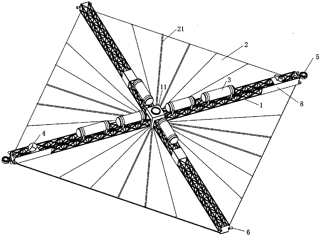
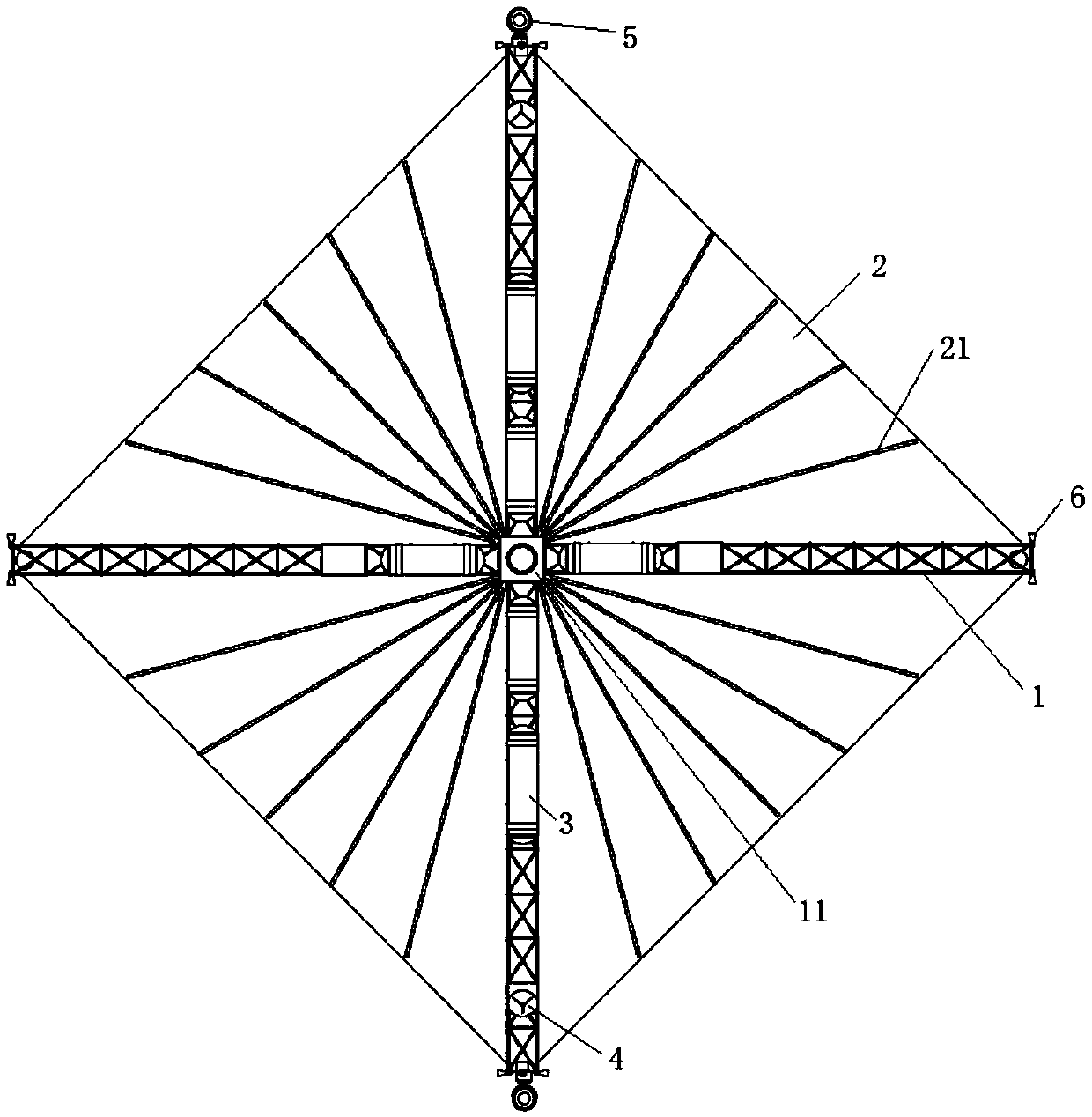
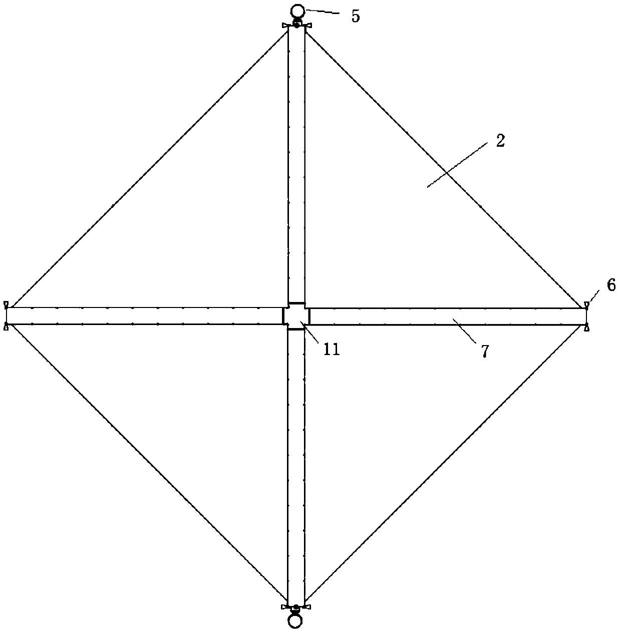
[0041] Please refer to figure 1 , figure 2 and image 3 , is a schematic diagram of the first embodiment of the present invention. Generally, the solar cell array can be regarded as an integral part of the spacecraft power supply subsystem, and can also be regarded as an integral part of the spacecraft structural mechanism subsystem. In the present invention, the solar cell array is regarded as the composition of the spacecraft structural mechanism subsystem, that is, the solar cell array is a part of the spacecraft platform, therefore, the truss type fully flexible spacecraft platform structure of the present invention is mainly composed of a truss structure 1 and expandable solar cell array 2 are composed of two parts.

[0042]In this embodiment, the mission goal is set to design a spacecraft with an electric power not less than 100 kilowatts. According to the preliminary calculation of the power generation efficiency of solar cells of 250 watts per square meter, the ar...

no. 2 example

[0053] Figure 11 A second embodiment of the invention is shown. As shown in the figure, the truss structure 1 is composed of three sides of equal length, and the included angle between each side is 120°, and there are three deployable solar cell arrays 2, which are respectively located in the area formed by the three truss sides. Each solar cell array has the same size, and the two sides of each solar cell array are connected to the truss structure 1 . The overall shape of the fully flexible spacecraft platform structure composed of the truss structure 1 and three deployable solar cell arrays 2 is an equilateral triangle configuration.

no. 3 example

[0055] Figure 12 A third embodiment of the invention is shown. As shown in the figure, the truss structure 1 is composed of five sides of equal length, and the angle between each side is 72°, and there are five deployable solar cell arrays 2, each of which has the same size, and Both sides of each solar battery array are connected with the truss structure 1 . The overall shape of the fully flexible spacecraft platform composed of the truss structure 1 and five deployable solar cell arrays 2 is a regular pentagon.


PUM


Abstract

The invention discloses a truss-type all-flexible spacecraft structure platform, belonging to the technical field of spacecraft structure design. The spacecraft structure platform adopts an expandabletruss structure formed by splicing a plurality of basic truss structure units as a main bearing structure, and a deployable solar array is laid on top of the truss structure to form a plane that canobtain sunlight. Various equipment loads carried on the spacecraft are installed by hanging under the truss or being arranged in cavities inside the basic truss units. Compared with the traditional spacecraft structure platform, the rigidity of the structure system is improved, the mass of the structure system is reduced, and the payload ratio of the system is greatly improved. In addition, the truss-type all-flexible spacecraft structure platform also has good expansibility, and can be assembled into various different configurations flexibly and conveniently to meet the needs of spacecraft design tasks of different scales.

Description

technical field [0001] The invention belongs to the technical field of spacecraft structure design, in particular to a truss type fully flexible spacecraft structure platform. Background technique [0002] Spacecraft, also known as space vehicles and space vehicles, mainly include artificial earth satellites, space probes, cargo spacecraft, manned spacecraft, and space stations. The structural platform of traditional spacecraft mostly adopts the structure of "central body + solar wings on both sides" (such as my country's "Dongfanghong 4" communication satellite, "Chang'e 2" lunar exploration satellite, etc.), or "central body + one-sided "Solar Wing" structure (such as my country's "Fengyun-3" meteorological satellite). The body of this type of spacecraft is a type of closed cabin structure with high rigidity, which can be regarded as a rigid body in dynamic analysis; while the solar wings arranged on both sides or one side of the body are relatively flexible, and are usual...

Claims


Application Information

Patent Timeline
Patent Type & Authority Applications(China)
IPC IPC(8): B64G1/22B64G1/44
CPCB64G1/22B64G1/443
Inventor 李东旭刘望王杰朱仕尧
Owner NAT UNIV OF DEFENSE TECH
Why Eureka
Try Eureka