Material pushing device

A technology of equipment and push rods, which is applied to conveyor objects, transportation and packaging, etc., can solve the problems of error-prone material extraction process and reduced material extraction efficiency, and achieve the effect of reducing error rate and improving material reclaiming efficiency.

Pending Publication Date: 2019-04-05
SHENZHEN JINZHOU PRECISION TECH
View PDF9 Cites 1 Cited by
  • Summary
  • Abstract
  • Description
  • Claims
  • Application Information

AI Technical Summary

Problems solved by technology

[0004] The purpose of the present invention is to provide a material pushing device, aiming to solve the technical problems in the prior art that the efficiency of material extraction is reduced due to manual material extraction by operators and the process of material extraction is prone to errors

Method used


Image

  • Material pushing device
  • Material pushing device
  • Material pushing device

Examples


Embodiment Construction

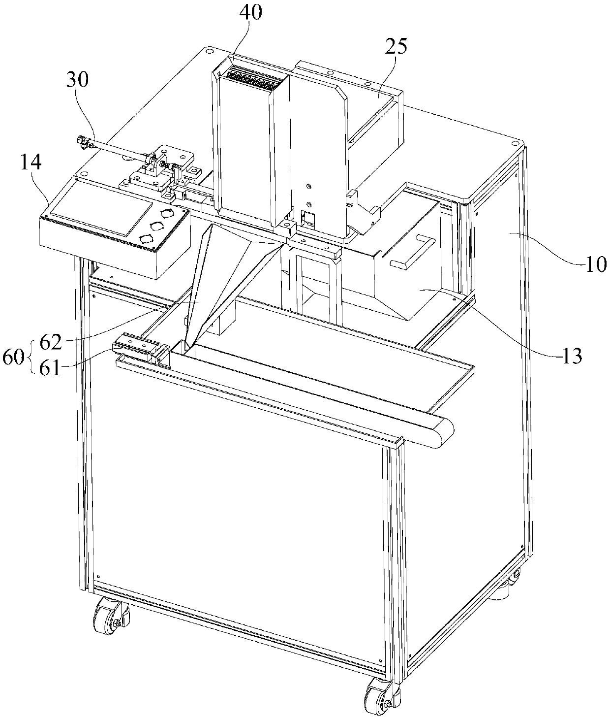
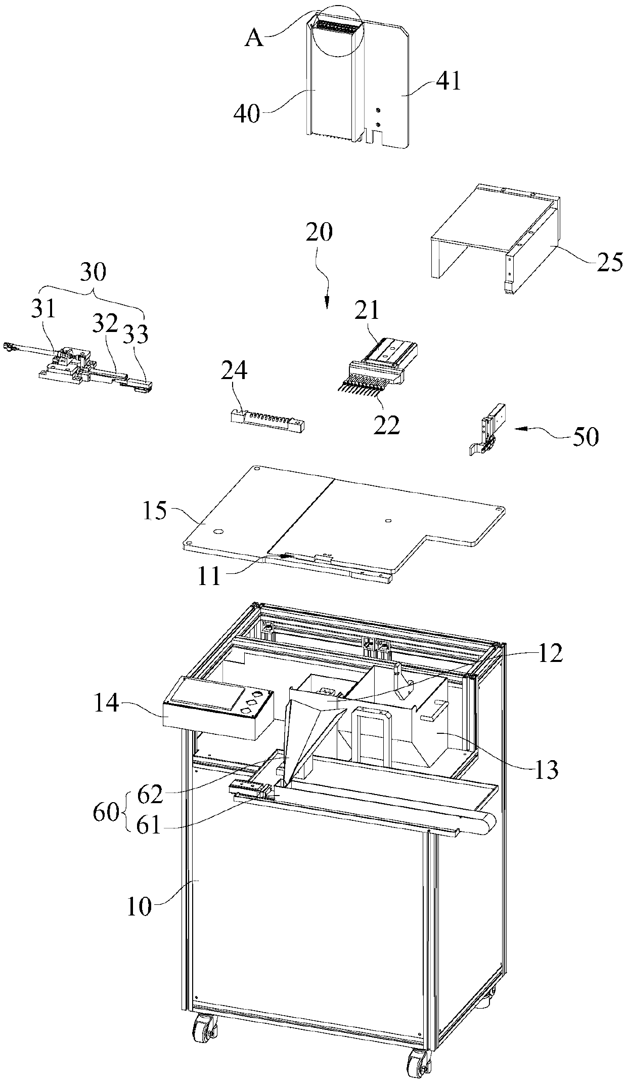
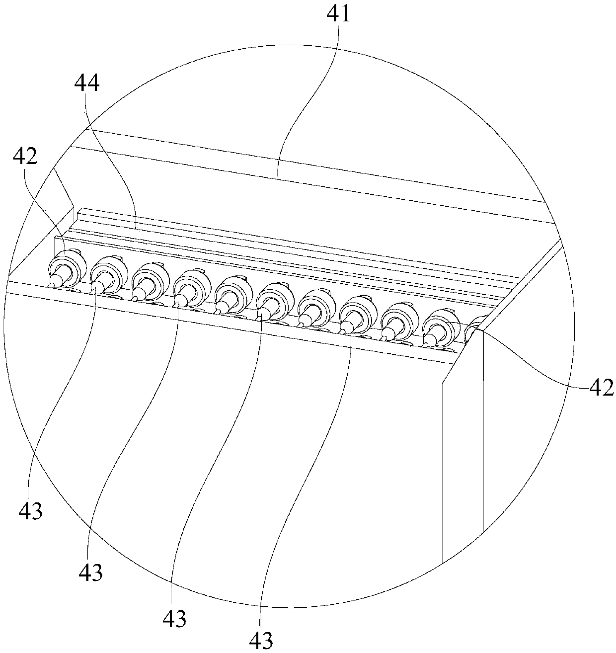
[0041] Embodiments of the present invention are described in detail below, examples of which are shown in the drawings, wherein the same or similar reference numerals designate the same or similar elements or elements having the same or similar functions throughout. Attached below by reference Figure 1-8 The described embodiments are exemplary and are intended to explain the present invention, but should not be construed as limiting the present invention.

[0042] In describing the present invention, it should be understood that the terms "length", "width", "upper", "lower", "front", "rear", "left", "right", "vertical", The orientation or positional relationship indicated by "horizontal", "top", "bottom", "inner", "outer", etc. are based on the orientation or positional relationship shown in the drawings, and are only for the convenience of describing the present invention and simplifying the description, rather than Nothing indicating or implying that a referenced device or...


PUM


Abstract

The invention belongs to the technical field of automatic equipment, and particularly relates to a material pushing device. The material pushing device comprises a rack, a material pushing mechanism and a die pushing mechanism, wherein the material pushing mechanism comprises a driving part and a plurality of material pushing rods; the driving part is mounted on the rack; each material pushing rodis mounted at the driving end of the driving part and is used for pushing out an outside bar to be pushed from an outer material box; the die pushing mechanism comprises a die pushing cylinder and atransverse pushing block; the die pushing cylinder is mounted on the rack; the transverse pushing block is mounted on a piston rod of the die pushing cylinder and is used for pushing the outer material box far away from a material pushing station after each material pushing rod finishes material pushing; each bar is pushed out through the corresponding material pushing rod, and an empty box without the bars is pushed away from the material pushing station corresponding to each material pushing rod through the transverse pushing block, and thus a space is supplied to the next material box, andthe operation is circularly carried out. With the adoption of the material pushing device, needle shaped or bar shaped parts can be automatically pushed, so that the picking efficiency of fine needleshaped or bar shaped parts can be obviously improved, and the error rate in the picking process is decreased.

Description

technical field [0001] The invention belongs to the technical field of automation equipment, and in particular relates to a material pushing equipment. Background technique [0002] For relatively small needle-shaped or rod-shaped parts, they are often inserted into packaging boxes for storage and transportation, because such parts are relatively small. The process of taking it out from the packing box is usually done by manual extraction by operators. [0003] However, only manually extracting the above-mentioned parts by the operator will not only lead to a slow picking speed of the parts and a decrease in efficiency, but also rely on the operator to manually extract the materials, which will also lead to errors in the extraction process of the parts and increase the rework rate. Contents of the invention [0004] The object of the present invention is to provide a material pushing device, aiming at solving the technical problems in the prior art that the efficiency of ...

Claims


Application Information

Patent Timeline
Patent Type & Authority Applications(China)
IPC IPC(8): B65G47/82
CPCB65G47/82
Inventor 陈雄建
Owner SHENZHEN JINZHOU PRECISION TECH
Why Eureka
Try Eureka