Heat exchange device

A heat exchange device, heat exchanger technology, applied in the direction of solar thermal energy, solar thermal power generation, solar thermal collectors, etc., can solve the problem of narrow application range, etc., to achieve the effect of reducing the ambient temperature

Inactive Publication Date: 2019-04-05
SIYUAN ELECTRIC APPLIANCES
View PDF3 Cites 2 Cited by
  • Summary
  • Abstract
  • Description
  • Claims
  • Application Information

AI Technical Summary

Problems solved by technology

[0002] Existing heat exchange devices usually use electric energy or thermal energy for heat exchange, but usually can only be used in fixed places and fields, and the scope of application is extremely narrow

Method used


Image

  • Heat exchange device
  • Heat exchange device

Examples


Embodiment Construction

[0018] The following will clearly and completely describe the technical solutions in the embodiments of the present invention with reference to the accompanying drawings in the embodiments of the present invention. Obviously, the described embodiments are only some, not all, embodiments of the present invention. Based on the embodiments of the present invention, all other embodiments obtained by persons of ordinary skill in the art without making creative efforts belong to the protection scope of the present invention.

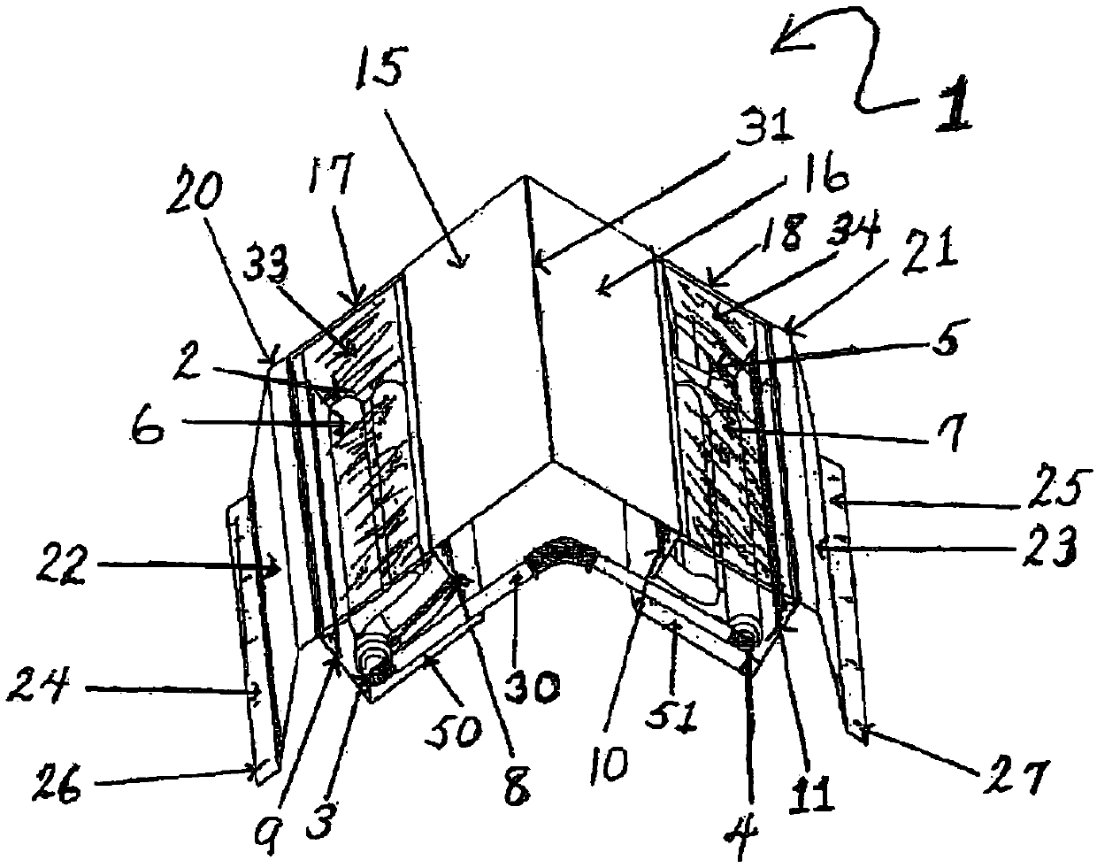
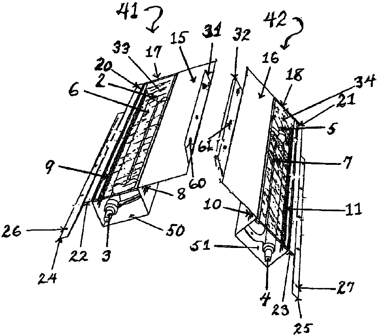
[0019] Such as Figure 1-2 As shown, the present invention provides a kind of technical scheme:

[0020] The heat exchanging device can be placed on the ridge vent, and the heat exchanging device has at least one heat exchanger, and each heat exchanger includes a water tank, wherein the water tank includes a pipeline. The heat exchange unit is mounted on a pitched roof with a typical structure and utilizing ridge vents. A roof deck is secured to a plurality ...


PUM


Abstract

The invention discloses a heat exchange device. The heat exchange device comprises at least two heat exchangers. Each heat exchanger comprises a water tank, a water inlet, a water outlet, a pipeline,a transparent cover, a reflecting surface, a solar collector, a rainfall baffle, a first heat conduction ventilation opening, a second heat conduction ventilation opening and an insect proof net; wherein the water tank is provided with a top, a bottom, a first end, a second end and two side surfaces; the water inlet is located in the first end of the water tank; the water outlet is located in thesecond end of the water tank; the pipeline is contained in the water tank, and the pipeline is connected with the water inlet and the water outlet; the transparent cover is located at the top of the water tank; the reflecting surface is located at the bottom of the water tank; the solar collector is connected to the first side of the water tank; the rainfall baffle is connected to the second sideof the water tank; and the first heat conduction ventilation opening is located in the first side of the water tank; the second heat conduction ventilation opening is located in the second side of thewater tank; and the insect proof net is connected to the rainfall baffle.

Description

technical field [0001] The invention relates to the technical field of heat exchange devices, in particular to a heat exchange device. Background technique [0002] Existing heat exchange devices usually use electric energy or thermal energy for heat exchange, but usually they can only be used in fixed places and fields, and the scope of application is extremely narrow. Contents of the invention [0003] (1) Solved technical problems [0004] Aiming at the deficiencies of the prior art, the present invention provides a heat exchange device to improve the scope of application of the existing heat exchange device. [0005] (2) Technical solution [0006] To achieve the above object, the present invention provides the following technical solutions: a heat exchange device comprising at least two heat exchangers, each heat exchanger comprising: a water tank, wherein the water tank has a top, a bottom, a first end, a second end, and two sides; a water inlet at the first end o...

Claims


Application Information

Patent Timeline
Patent Type & Authority Applications(China)
IPC IPC(8): F24S10/30F24S23/70F24S40/00F24S40/44F24S80/00F24S25/61F24S25/67
CPCY02E10/44Y02E10/47
Inventor 徐宁向熹
Owner SIYUAN ELECTRIC APPLIANCES
Why Eureka
Try Eureka