Energy storage system

An energy storage system and subsystem technology, applied in the field of battery cluster temperature control, can solve the problems of reduced service life of the energy storage system, unfavorable stable operation of batteries, damage of connecting parts, etc., and achieves improved heat conduction efficiency and uniformity, energy consumption The effect of less and convenient layout

Pending Publication Date: 2021-11-16
上海禾徐科技发展有限公司
View PDF0 Cites 0 Cited by
  • Summary
  • Abstract
  • Description
  • Claims
  • Application Information

AI Technical Summary

Problems solved by technology

In order to flow the coolant through the liquid-cooled pipes provided at the bottom of each battery pack and ensure the flow rate of the coolant, it is necessary to pressurize the drive components (such as the cooling pump), resulting in excessive power required by the drive components (such as the cooling pump) , and because there are some connecting parts between the main liquid cooling pipe and the internal cooling pipe of each battery pack in the whole liquid cooling system, high pressure can easily cause damage to these connecting parts; and the method of liquid cooling can only be used for the battery The end connected to the liquid cooling pipe is used for cooling. The cooling of the other ends of the battery mainly depends on the conduction cooling of the battery case. The practical effect is not good. There is a large temperature difference between the two ends of the battery, which is not good for the long-term stable operation of the battery. Resulting in discounted service life of the energy storage system

Method used


Image

  • Energy storage system
  • Energy storage system
  • Energy storage system

Examples


Embodiment Construction

[0046] In order to make the purpose, technical solutions and advantages of the present invention clearer, the present invention will be further described in detail below in conjunction with the accompanying drawings. Obviously, the described embodiments are only some of the embodiments of the present invention, rather than all of them. Based on the embodiments of the present invention, all other embodiments obtained by persons of ordinary skill in the art without making creative efforts belong to the protection scope of the present invention.

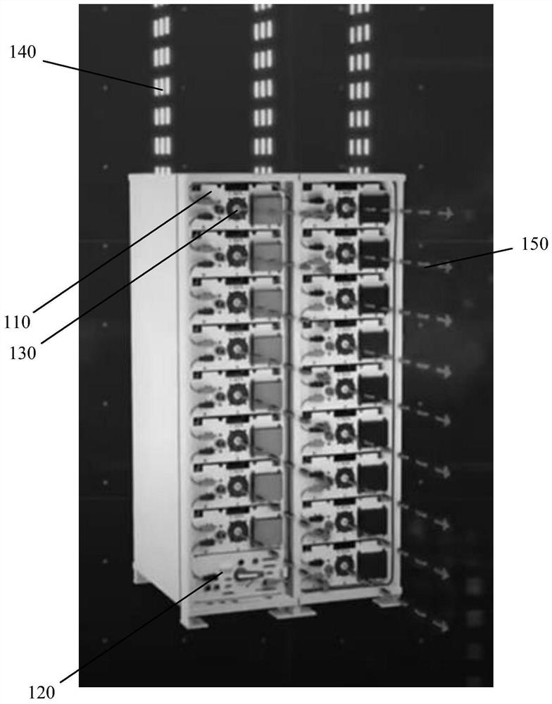
[0047] At present, battery energy storage is one of the solutions for important commercial energy storage systems. Taking lithium batteries as an example, usually multiple (such as hundreds of) battery cells are connected in series or in parallel to form a battery cluster. One or more Clusters of batteries form an energy storage system. Wherein, the battery pack includes a plurality of battery packs, that is, a battery pack, that is, a ...


PUM


Abstract

The invention discloses an energy storage system which comprises a battery cluster and an air-liquid mixing temperature control system. The air-liquid mixing temperature control system comprises an air cooling subsystem and a liquid cooling subsystem; the liquid cooling subsystem comprises a driving part and a liquid cooling pipeline filled with cooling liquid; the air cooling subsystem comprises an outer machine frame of any battery pack in the battery cluster, an air duct communicated with an air inlet and an air outlet arranged in the air cooling subsystem, and a fan; the driving part is used for driving the cooling liquid in the liquid cooling pipeline to flow; the liquid cooling pipeline is arranged on the outer surface of the battery cluster; the air duct is used for providing a flowing channel for air flowing into the battery pack; and the fan is used for driving air in the battery pack so as to control the temperature of the battery. According to the energy storage system and the air-liquid mixing temperature control system matched with the energy storage system, the uniformity control level of the temperature of each battery in the energy storage system can be improved, the uniformity temperature control level of different surfaces of the batteries can be improved, the service life of the energy storage system is prolonged, and the working efficiency of the energy storage system is improved.

Description

technical field [0001] The invention relates to the technical field of battery cluster temperature control, in particular to an energy storage system. Background technique [0002] In the prior art, the applicable fields of batteries include telecommunications, audio / video, surveillance, industrial automation, transportation, robotics, military, medical, instrumentation and other industrial fields. Such as aerospace applications and large-scale energy storage and electric vehicles, submarine earthquake and tsunami monitoring, space exploration and military applications. [0003] At present, in order to improve the charging and discharging performance and efficiency of batteries, multiple batteries are generally connected in series or in parallel to form a battery pack, and then multiple battery packs are combined to form a battery cluster, and one or more battery clusters form an energy storage system for charging and discharging. . Since the battery will generate heat dur...

Claims


Application Information

Patent Timeline
IPC IPC(8): H01M10/613H01M10/655H01M10/6554H01M10/6563H01M10/6568
CPCH01M10/613H01M10/6563H01M10/6568H01M10/655H01M10/6554Y02E60/10
Inventor 徐思涵
Owner 上海禾徐科技发展有限公司
Why Eureka
Try Eureka