Capacitor

A technology of capacitors and heat pipes, which is applied in the field of capacitors, can solve problems such as unsolved heat dissipation problems of capacitors, and achieve the effect of reducing temperature difference and increasing ambient temperature

Active Publication Date: 2013-02-13
GUANGDONG SHUNRONG ELECTRIC
View PDF6 Cites 12 Cited by
  • Summary
  • Abstract
  • Description
  • Claims
  • Application Information

AI Technical Summary

Problems solved by technology

CN2517091Y discloses an external cooling type electric heating capacitor, which describes that the heat-absorbing end of a radiator such as a heat pipe is inserted into the capacitor, and the heat-dissipating end is inserted into an external cooler, so as to export the heat inside the capacitor. Carefully study the specification of this public document The text and drawings, combined with the comparative technology CN2170570Y used in this document, it can be known that this technology moves the radiator in the capacitor cover to the outside of the cover, and the heat pipe is only inserted into the inside of the cover and connected with the heating part of the capacitor. Part of it is actually the heating part on the outer surface of the capacitor in the cover shell. Its essence is still to solve the heat dissipation problem on the outer surface of the capacitor in the cover shell, and the heat dissipation problem inside the capacitor has not been solved yet.

Method used


Image

  • Capacitor
  • Capacitor
  • Capacitor

Examples


Embodiment 1

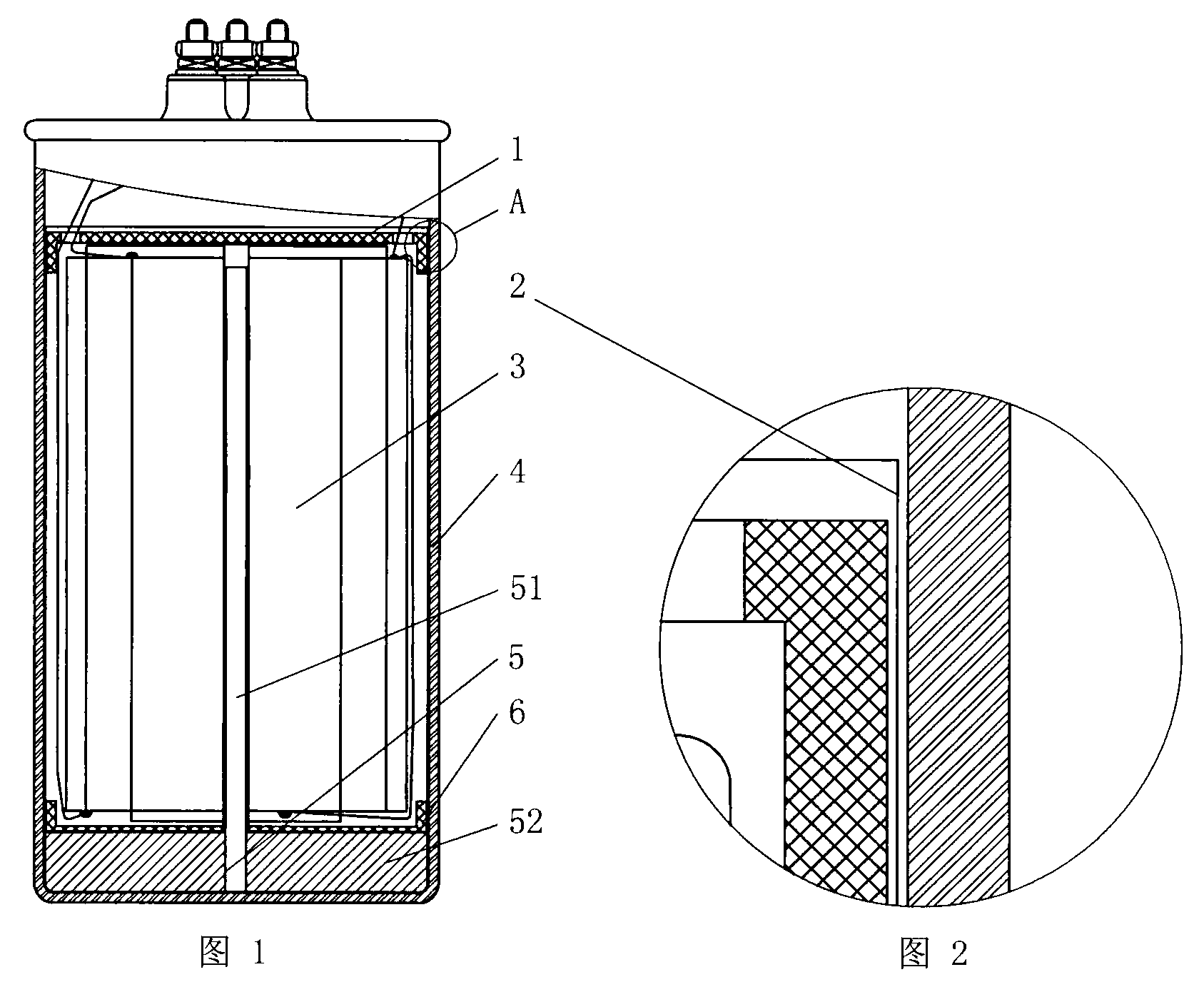
[0018] see figure 1 with figure 2 The capacitor includes an upper positioning sleeve 1, an insulating paper 2, a core 3, a shell 4, a heat pipe device 5, and a lower positioning sleeve 6. The capacitor is cylindrical, and the heat pipe device 5 is composed of a heat pipe 51 and a heat conduction block 52. The heat pipe 51 is located on In the center of the core, the heat conduction block 52 is installed at the lower end of the heat pipe 51. The core is wrapped by the upper positioning sleeve 1, the lower positioning sleeve 6 and the insulating paper 2. The heat pipe 51 is closely connected to the center of the core 3 and the center of the heat conduction block 52 respectively. Contact, the outer cylindrical surface and the bottom surface of the heat conduction block 52 are in close contact with the shell, so that the heat in the center of the core 3 is transferred to the shell 4 through the heat pipe 51 and the heat conduction block 52 for heat exchange with the outside world...

Embodiment 2

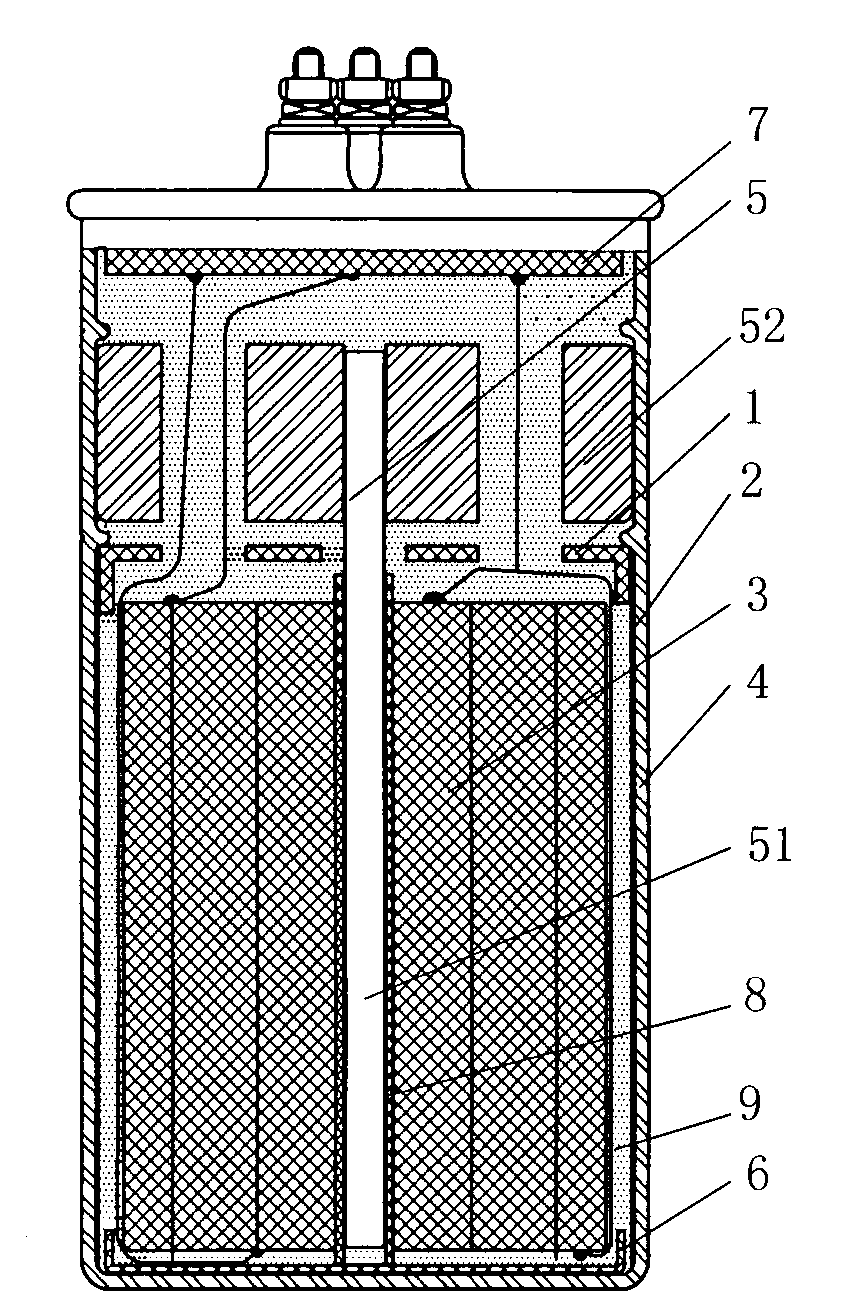
[0020] see image 3 , the capacitor shown is an explosion-proof metallized film capacitor, the metallized film is wound on the mandrel 8 to form the core 3, the top of the capacitor is also provided with an explosion-proof device 7, the heat pipe 51 is located in the mandrel 8, and is connected with the mandrel 8 close contact, the capacitor is cylindrical, and the gap in the shell 4 is filled with filler 9, so that the upper positioning sleeve 1, insulating paper 2, core 3, shell 4, heat pipe device 5, lower positioning sleeve 6 and other components are in the The shell 4 is fixed inside, the heat pipe device 5 is a gravity heat pipe, and the heat conduction block 52 is installed on the upper end of the heat pipe 51. When the core 3 works, the internal temperature of the capacitor rises, and the working fluid at the bottom of the heat pipe 51 is vaporized and raised to the top of the heat pipe 51 , the heat carried by the steam is transferred to the shell 4 through the heat c...

Embodiment 3

[0022] see Figure 4 , single heat pipe 51 has constituted heat pipe device, and heat pipe 51 is installed in the bottom of shell 4, and heat pipe 51 is in close contact with the surface of the mounting position of shell 4, and the heat of the center of core 3 is directly transferred to shell 4.


PUM


Abstract

The invention relates to a capacitor. Internal heat is conducted out via a heat pipe, the temperature difference between the interior and the surface of the capacitor is reduced, so that the reliability of the capacitor is increased, and the service life is prolonged. The capacitor comprises a core formed by rolling, a heat pipe device, a shell, a locating sleeve and insulating paper, wherein the heat pipe of the heat pipe device is arranged in the center of the core. The heat in the center of the capacitor is conducted to the surface of the capacitor in time by using the heat transfer principle of the heat pipe, so that the temperature difference between the interior and the surface of the capacitor is reduced, and the environment temperature borne by the capacitor is increased.

Description

Technical field: [0001] The invention relates to a capacitor, in particular to a power capacitor using a heat pipe to dissipate heat. Background technique: [0002] When the capacitor is working, it will generate heat to increase the internal temperature of the capacitor. If the internal temperature of the capacitor is too high during operation, it will accelerate the aging of the capacitor and cause the capacitor to be damaged prematurely. At present, there are many ways to solve the heat dissipation problem of capacitors, including water cooling and air cooling, among which heat pipe technology has also been adopted, but most of the technologies solve the problem of heat dissipation on the surface of capacitors. For example, CN102013319A discloses a high-power capacitor heat dissipation The device solves the problem of heat dissipation on the surface of the capacitor. However, the highest operating temperature of the capacitor lies inside the capacitor. Experiments have p...

Claims


Application Information

Patent Timeline
Patent Type & Authority Applications(China)
IPC IPC(8): H01G2/08
Inventor 骆家星张业清马明军
Owner GUANGDONG SHUNRONG ELECTRIC
Why Eureka
Try Eureka