Hot air supply device for quick deicing and snow removing system at bottom of high-speed rail train

A technology for air supply device and train, which is applied in the direction of vehicle exterior cleaning device, railway auxiliary equipment, etc., to reduce the workload of manual snow removal, improve reliability and effectiveness, and improve efficiency.

Inactive Publication Date: 2014-06-25
CHINA RAILWAY DESIGN GRP CO LTD
View PDF5 Cites 12 Cited by
  • Summary
  • Abstract
  • Description
  • Claims
  • Application Information

AI Technical Summary

Problems solved by technology

[0004] Aiming at the existing problems of ice melting and snow removal at the bottom of high-speed rail trains, the present invention introduces a hot air supply device for the rapid ice melting and snow removal system at the bottom of high-speed rail trains. The air supply column of the four-way adjustment locking device is set on one side of the ice melting and snow removal station of the train, blowing hot air directly to the bottom of the train, and making the hot air fully cover the ice and snow. , improve the reliability and effectiveness of the hot air melting ice and snow removal system, improve the efficiency of the hot air melting ice and snow removal system, meet the requirements of the process, and improve energy utilization

Method used


Image

  • Hot air supply device for quick deicing and snow removing system at bottom of high-speed rail train
  • Hot air supply device for quick deicing and snow removing system at bottom of high-speed rail train
  • Hot air supply device for quick deicing and snow removing system at bottom of high-speed rail train

Examples


Embodiment Construction

[0023] The technical solution of the present invention is further described in conjunction with the accompanying drawings.

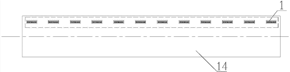
[0024] figure 2 The installation status of the blowing column of the hot air blowing device according to the present invention is shown. Such as figure 2 as shown,

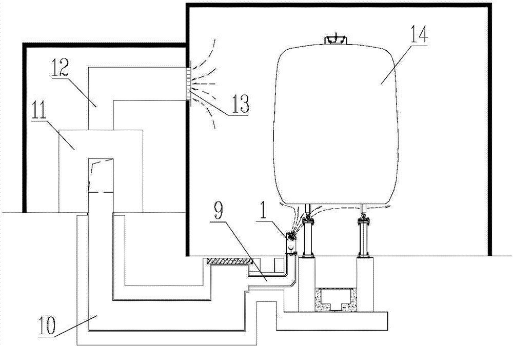
[0025] The air supply column 1 of the hot air supply device for the rapid ice melting and snow removal system at the bottom of the high-speed rail train involved in the present invention is arranged on the ground on one side of the high-speed rail train body 14 parked at the ice melting and snow removal station, corresponding to a train body Arrange 11 to 13 air supply columns 1 evenly in a row, and the distance between the air supply columns 1 and the center of the track is controlled between 1200mm and 1400mm. The opening of the air branch pipe 9 on the ground is fixed by a flange connection. These air-supply pillars corresponding to a train body just constitute a set of hot-blast ai...


PUM


Abstract

The invention discloses a hot air supply device for a quick deicing and snow removing system at the bottom of a high-speed rail train. The hot air supply device comprises air supply columns arranged on one side of a deicing and snow removing station of the train, the air supply columns are lined up on the ground and evenly arranged, and 11-13 air supply columns are arranged corresponding to each section of train body. The air supply columns are fixed to the ground, communicated with an underground civil engineering delivery conduit and connected with a hot air unit in a hot air machine room through the underground civil engineering delivery conduit. Each air supply column of the hot air supply device comprises a column body, an air supply port, an air supply angle four-way regulating and locking device and an air quantity regulating valve, the air supply port is arranged on the top of the air supply column, and the air supply angle four-way regulating and locking device is arranged in the air supply port. According to the hot air supply device, hot air at a certain speed is blown out towards the bottom of the train through the air supply columns, heat exchange between ice and snow and the train body can be enhanced and the overall environment temperature of a garage can be improved through the air supply temperature and flowing of the hot air, and the functions of quick deicing and snow removing can be achieved. According to the hot air supply device, it can be guaranteed that the longest deicing operating time at the bottom of the compartment of the train is less than one hour, and technological requirements can be met.

Description

technical field [0001] The invention relates to a high-speed train maintenance device, in particular to a hot air supply device for a system for melting ice and snow at the bottom of a train compartment. Background technique [0002] During the high-speed running of high-speed trains in ice and snow areas in winter, a large amount of ice and snow will be sucked up and attached to the bottom of the carriage, forming a dense layer of ice and snow, usually with a thickness of more than 8cm. Every time a high-speed rail train runs for 4,000 kilometers or runs for 48 hours, it needs to return to the bullet train station for a first-level inspection. Each first-level inspection should be completed within 3.5 hours. First, it is necessary to quickly remove the ice and snow attached to the bottom of the carriage to achieve ice and snow removal. As for the departure standard, there must be no residual ice and snow accumulation on all parts of the train running part, so as to ensure t...

Claims


Application Information

Patent Timeline
Patent Type & Authority Applications(China)
IPC IPC(8): B60S3/04B61K13/00
Inventor 孙兆军朱建章黄保民李杰高辉李桂萍
Owner CHINA RAILWAY DESIGN GRP CO LTD
Why Eureka
Try Eureka