Brushless direct-current magnetic water pump

A water pump and magnetic force technology, which is applied to pumps, parts of pumping devices for elastic fluids, pump devices, etc., can solve the problems of high dustproof and waterproof levels, poor dustproof and waterproof effects, and reduced service life of motors. To achieve the effect of improving life and using ambient temperature, good protection, reasonable and effective cycle

Active Publication Date: 2015-11-18
河北深海电器有限公司
View PDF4 Cites 12 Cited by
  • Summary
  • Abstract
  • Description
  • Claims
  • Application Information

AI Technical Summary

Problems solved by technology

The disadvantage of this structure is that the air inlet of the motor casing directly communicates with the rotor parts inside the motor, the dustproof and waterproof effects are poor, and the application is limited to a certain extent, and the service life of the motor is greatly reduced during use.
[0003] The second prior art also uses air cooling to dissipate heat from the electronic reversing control board. The control board is installed at the bottom of the motor housing, but the motor housing is not provided with air inlets and outlets, and the inside and outside of the motor housing are completely isolated. , so the dustproof and waterproof level is high
Although the dustproof and waterproof performance of this structure is better, it can only balance the heat of the control board, and the heat dissipation still depends on the natural heat dissipation of the motor shell, and the heat dissipation effect is not obvious, especially when the working environment temperature of the motor is high (such as above 100°C) ), it is impossible to dissipate heat to the control board in the motor. The motor runs under the condition of high ambient temperature and poor heat dissipation effect, which will reduce the life of the control board, which will also reduce the service life of the motor and even the water pump.

Method used


Image

  • Brushless direct-current magnetic water pump
  • Brushless direct-current magnetic water pump
  • Brushless direct-current magnetic water pump

Examples


Embodiment Construction

[0041] In order to have a clearer understanding of the technical features, purposes and effects of the present invention, the specific implementation manners of the present invention will now be described with reference to the accompanying drawings.

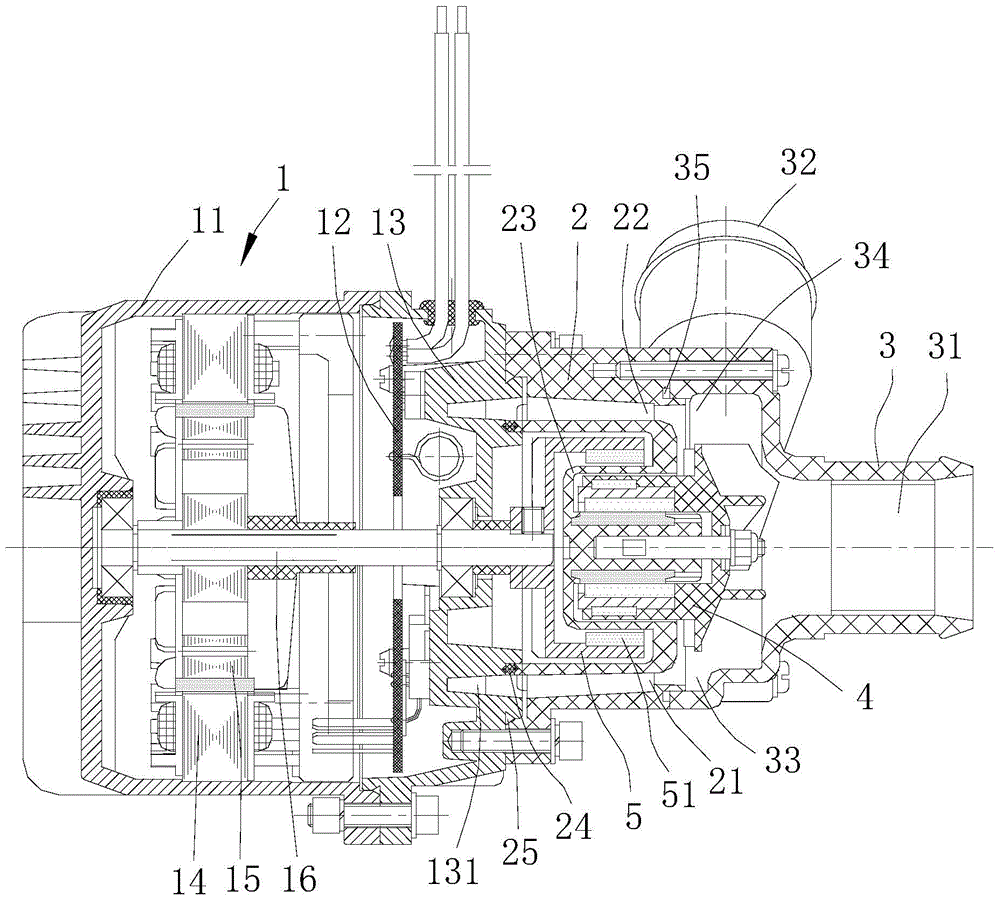
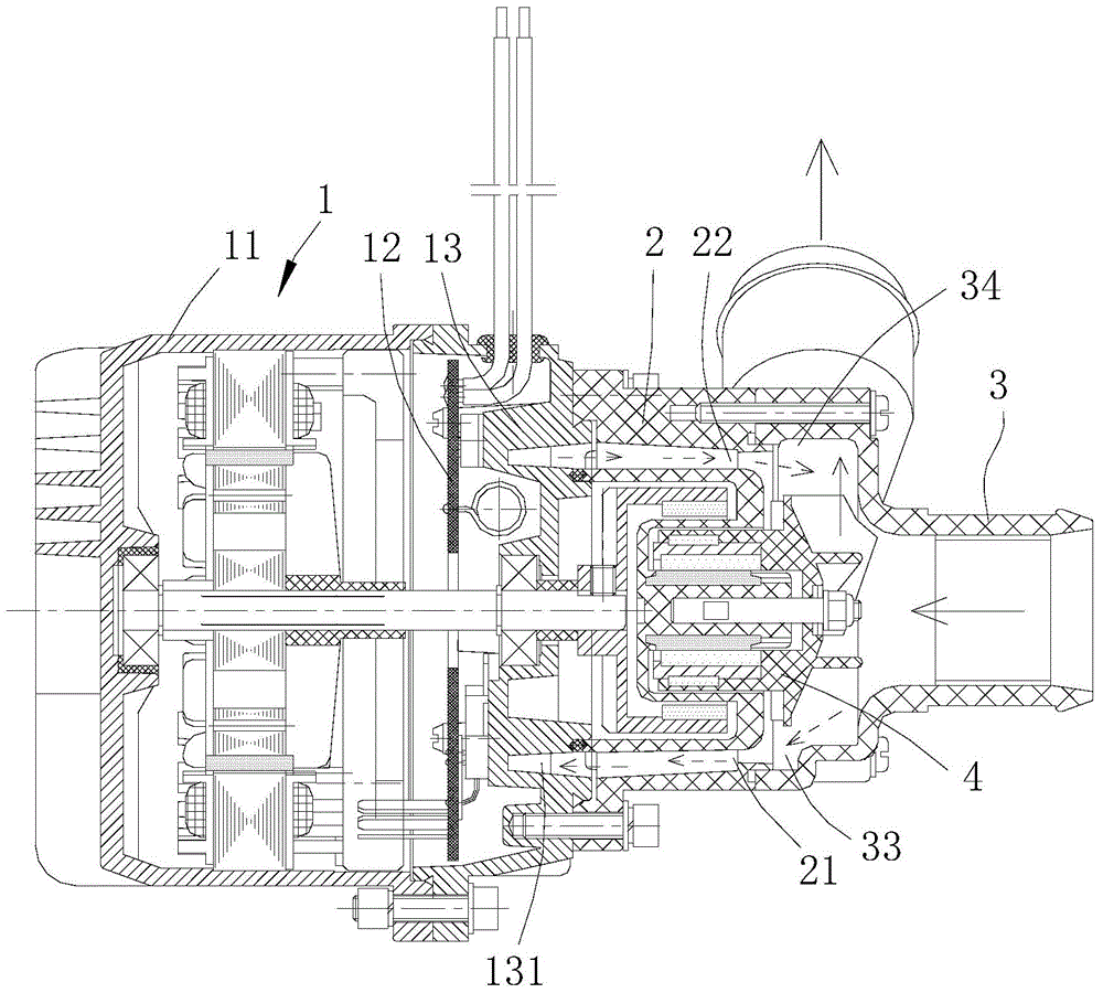
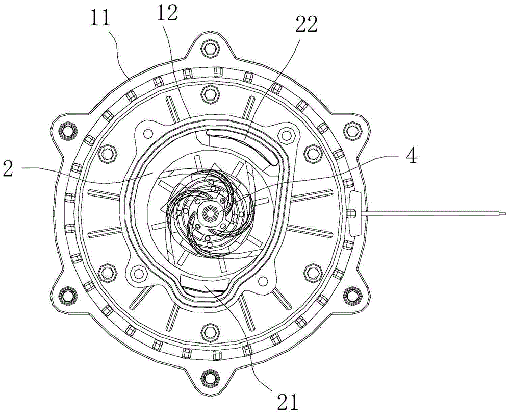
[0042] like figure 1 , Image 6 , Figure 7 As shown, the present invention provides a brushless DC magnetic water pump, which includes a brushless DC motor 1 , a pump base 2 , a pump cover 3 and an impeller 4 . The brushless DC motor 1 comprises a hollow motor housing 11, an electronic commutation control board 12 located in the motor housing 11, and an end cover 13 (or front end cover) that is sealed and connected to the end of the motor housing 11. The end cover 13 and the motor casing 11 are connected by bolts and sealed by a sealing ring, and the electronic commutation control board 12 is installed on the inner end surface of the end cover 13 (the inner end surface is the end surface facing the inside of the motor casing 1...


PUM


Abstract

The invention provides a brushless direct-current magnetic water pump. The brushless direct-current magnetic water pump comprises a brushless direct-current motor, a pump seat, a pump cover and impellers. The brushless direct-current motor comprises a hollow motor shell, an electronic reversing control panel in the motor shell, and an end cover connected to one end of the motor shell in a sealed mode. The electronic reversing control panel is installed on the inner end face of the end cover, and a cooling water chamber for cooling the electronic reversing control panel is arranged on the outer end face of the end cover. One end of the pump seat is connected with the outer end face of the end cover in a sealed mode. The pump seat is provided with a water inflow hole and a water drainage hole which are communicated with the cooling water chamber respectively. The water inflow hole, the cooling water chamber and the water drainage hole form a fluid flow channel. The pump cover is connected with the other end of the pump seat in a sealed mode. An inner cavity is formed in the pump cover and communicated with the water inflow hole and the water drainage hole of the pump seat. Heat generated by the electronic reversing control panel is forcibly circulated and brought out in an end face water-cooling mode, the control panel can be cooled effectively and rapidly, the cooling performance of the motor is improved, and the service life of the motor is prolonged.

Description

technical field [0001] The invention relates to the field of water pumps, in particular to a brushless direct current magnetic force water pump which dissipates heat to a control board of a direct current brushless motor through end surface water cooling. Background technique [0002] The brushless DC magnetic water pump is equipped with a brushless DC motor, which drives the impeller to rotate. The heat dissipation of the electronic components of the brushless DC motor's control board directly affects the performance of the motor. The first prior art adopts forced air cooling to dissipate heat for the electronic commutation control board, that is, the control board is installed at the bottom of the motor housing, the motor housing is provided with an air inlet and an air outlet, and the rotor part is equipped with a cooling fan. After the motor is running, the cooling fan will inhale the wind from the air inlet and discharge it from the air outlet to achieve the air cooling...

Claims


Application Information

Patent Timeline
Patent Type & Authority Applications(China)
IPC IPC(8): F04D13/06F04D29/42H02K5/20
Inventor 门少国伊奇才
Owner 河北深海电器有限公司
Why Eureka
Try Eureka