A Radar Refined Ranging Method

A ranging method and radar technology, applied in measurement devices, radio wave measurement systems, instruments, etc., can solve the problems of difficult data transmission rate to meet requirements, increase the cost of radar system, rough signal processing process, etc., achieve low sampling rate, Meet the data transmission requirements, the effect of less data volume

Active Publication Date: 2020-09-01
JINGZHOU NANHU MACHINERY CO LTD
View PDF10 Cites 0 Cited by
  • Summary
  • Abstract
  • Description
  • Claims
  • Application Information

AI Technical Summary

Problems solved by technology

However in T e Under the same pulse width condition, the FM bandwidth B The larger the waveform design is, the more difficult it is, and the higher the requirements for system hardware design; moreover, the frequency modulation bandwidth B The larger the sampling frequency f s The higher the value, the greater the amount of data, which requires a higher data transmission rate and signal processing rate. For this reason, better data transmission hardware and signal processing chips need to be configured, which greatly increases the cost of the radar system.
The traditional ranging method generally only samples once, and the amount of sampled data is large. When the signal bandwidth is increased, the difficulty of waveform design increases, the amount of data increases, and the data transmission rate is difficult to meet the requirements; and the signal processing process is rough—traditional ranging The method does not perform interpolation and digital filtering, but directly obtains the maximum position of the target in the distance dimension after obtaining the target envelope, and calculates the distance corresponding to this point, so as to obtain the target distance information
In this way, in order to achieve the purpose of increasing the signal bandwidth, improving the data transmission rate and ranging accuracy, the traditional ranging method must be supported by a higher standard waveform design and hardware system design. The requirements for corresponding sampling and data processing chips It is also higher, resulting in difficulties in design and production, and greatly increasing the cost of equipment

Method used


Image

  • A Radar Refined Ranging Method
  • A Radar Refined Ranging Method
  • A Radar Refined Ranging Method

Examples


Embodiment Construction

[0039] Below in conjunction with accompanying drawing, the embodiment of this radar refinement ranging method is described in further detail: (see Figure 1~5 ):
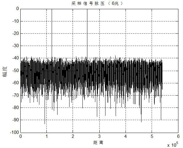
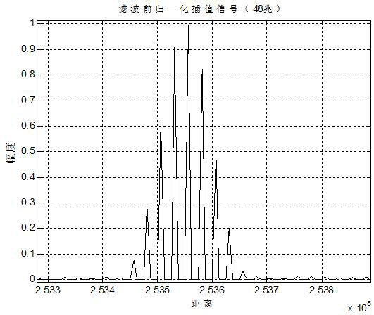
[0040]The design idea of ​​the present invention is: aiming at the deficiencies of the existing traditional ranging technology, in order to obtain higher ranging accuracy and higher distance resolution, the present invention improves the radar signal processing technology; the present invention includes two Sampling, and added interpolation, digital filtering and distance compensation process in the signal processing process; the present invention samples the radio frequency signal with a high sampling frequency; the sampling signal and the local oscillator signal are mixed and digitally filtered to obtain the baseband signal; The low sampling frequency re-samples the generated baseband signal, that is, signal extraction; considering that the detection target of the radar is usually a moving target, and the movement...


PUM


Abstract

The invention relates to a radar refinement ranging method, and belongs to the technical field of radar signal processing. The ranging signal processing flow of the method comprises the following steps: radio frequency sampling, mixing and filtering, low-sampling frequency re-sampling, speed measurement and distance compensation, pulse pressure and interpolation, filtering and distance compensation. Under the premise of not improving the waveform design difficulty and higher hardware design requirements, the data transmission rate is high, the distance measurement accuracy is improved, the radar working performance is improved, and the radar production cost is reduced. The method solves the problems that the existing ranging mode is only used for sampling once, resulting in large samplingdata amount, increased waveform design difficulty when the signal bandwidth is increased, increased data amount, and difficult requirement meeting of the data transmission rate, and that the signal processing is rough, and if requiring increased signal bandwidth, improved data transmission rate and ranging accuracy, higher standard waveform design and hardware design support are requested, and higher requirements for corresponding sampling and data processing chips are also requested, resulting in difficulty in design and fabrication, and increased equipment cost.

Description

technical field [0001] The invention relates to a radar refined ranging method, which belongs to the technical field of radar signal processing. Background technique [0002] Signal processing is one of the core technologies of modern radar systems, and ranging is an important part of signal processing. The quality of ranging directly affects the accuracy of radar detection target distance. An important parameter to measure and reflect the radar detection distance accuracy is the distance resolution, [0003] The distance resolution formula is as follows: [0004] [0005] In the formula, B Indicates the bandwidth; T e Indicates the transmitted pulse width or the equivalent pulse width after pulse compression; c is the electromagnetic wave propagation speed; visible, pulse width T e The narrower, that is, the frequency modulation bandwidth of the transmitted signal B The wider the distance resolution DR Also higher. However in T e Under the same pulse width co...

Claims


Application Information

Patent Timeline
Patent Type & Authority Patents(China)
IPC IPC(8): G01S13/28
CPCG01S13/282
Inventor 张龙涛沈佳波杜昌友管晓玲
Owner JINGZHOU NANHU MACHINERY CO LTD
Why Eureka
Try Eureka