Connector and signal transmission structure thereof

A connector and signal technology, applied in the direction of connection, connecting device parts, contact parts, etc., can solve the problems affecting signal transmission and signal crosstalk of high-speed connectors, so as to ensure the quality of signal transmission, reduce signal crosstalk, and avoid signal crosstalk. The effect of crosstalk

Active Publication Date: 2019-04-05
CHINA AVIATION OPTICAL-ELECTRICAL TECH CO LTD
View PDF6 Cites 2 Cited by
  • Summary
  • Abstract
  • Description
  • Claims
  • Application Information

AI Technical Summary

Problems solved by technology

Although the two adjacent signal pairs in the same column of this high-speed connector are separated by grounding signals to achieve shielding between the two adjacent signal pairs, the two adjacent signal pair

Method used


Image

  • Connector and signal transmission structure thereof
  • Connector and signal transmission structure thereof
  • Connector and signal transmission structure thereof

Examples


Embodiment Construction

[0038] Embodiments of the present invention will be further described below in conjunction with the accompanying drawings.

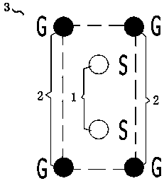
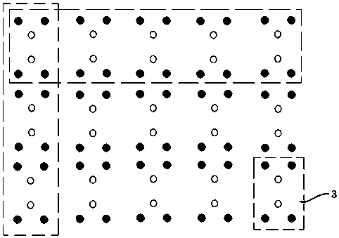
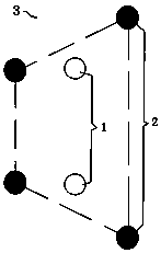
[0039] The first embodiment of the connector of the present invention specifically refers to a differential connector, of course, in other implementation manners, it is not limited to the differential connector. The connector of the present invention includes a connector housing, an insulator is arranged in the connector housing, and a signal pair unit 3 is installed in the insulator, such as figure 1 As shown; a plurality of signal pair units 3 are arranged according to certain rules to form a signal transmission structure, such as figure 2 shown.

[0040]The signal pair unit 3 includes a signal pair composed of two signal contacts 1 arranged at intervals. The outer periphery of the signal pair has a set quadrilateral area. It should be noted that the quadrilateral area is a virtual space area for more convenient description made the definition. The...


PUM


Abstract

The invention provides a connector and a signal transmission structure. The connector comprises a connector shell, wherein at least one signal pair unit is arranged in the connector shell, the signalpair unit comprises a signal pair, the signal pair comprises two signal contact pieces which are arranged at intervals, a set polygonal region is arranged at the periphery of the signal pair comprising the two signal contact pieces, the signal pair unit also comprises grounding contact pieces, and each grounding contact piece is arranged at a position of each corner of the polygonal region and isused for encircling the signal pair. The signal pair contained in the signal pair unit of the connector is encircled by the grounding contact pieces encircling to form the polygonal region, thus, thesignal pair can be shielded very well by the grounding contact pieces, signal crosstalk between two signals is prevented, the signal crosstalk of the connector is greatly reduced, and the signal transmission quality is ensured.

Description

technical field [0001] The invention relates to a connector and its signal transmission structure. Background technique [0002] Crosstalk refers to the undesired voltage noise interference on adjacent transmission lines due to electromagnetic coupling when a signal propagates on a transmission line. Signals are transmitted in the transmission line in the form of electromagnetic waves. Electromagnetic waves include time-varying electric and magnetic fields. The transformed electric and magnetic fields will generate induced voltages and currents in the surrounding transmission lines. The voltage and current are the direct causes of the crosstalk behavior in the disturbed transmission line. [0003] Crosstalk is another important factor affecting the transmission performance of products. Reducing crosstalk has always been an important direction in the design of high-speed connectors. In some cases, its importance to high-speed performance transmission even exceeds the charact...

Claims


Application Information

Patent Timeline
IPC IPC(8): H01R13/6471H01R13/02
CPCH01R13/02H01R13/6471
Inventor 袁俊峰马陆飞
Owner CHINA AVIATION OPTICAL-ELECTRICAL TECH CO LTD
Why Eureka
Try Eureka