Oscillator and chip

A technology of oscillator and comparator, which is applied in the direction of pulse generation, electrical components, and electric pulse generation. It can solve the problems of complex circuit design, increase of layout area, and increase of cost, so as to save chip area, reduce cost, and save circuit. Effects of Design Complexity

Inactive Publication Date: 2019-04-05
GREE ELECTRIC APPLIANCES INC
View PDF4 Cites 1 Cited by
  • Summary
  • Abstract
  • Description
  • Claims
  • Application Information

AI Technical Summary

Problems solved by technology

[0004] The purpose of the present invention is to overcome the technical problems of using two comparators to increase the layout area, increase the cost and complicate circuit design in the prior art, and provide an oscillator and its chip

Method used


Image

  • Oscillator and chip
  • Oscillator and chip
  • Oscillator and chip

Examples


Embodiment Construction

[0021] The technical solutions in the present invention will be clearly and completely described below in conjunction with the drawings in the embodiments of the present invention. Obviously, the described embodiments are only part of the embodiments of the present invention, not all of them.

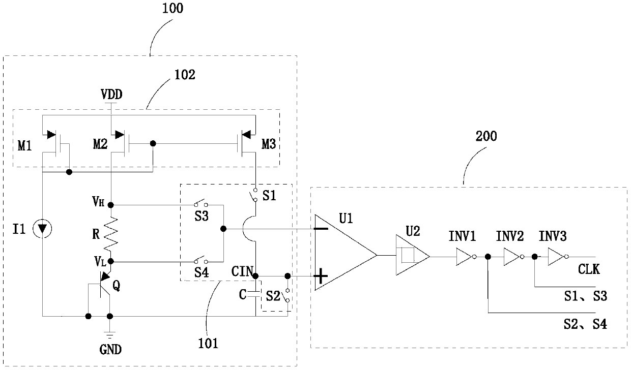
[0022] Such as figure 1 As shown, an oscillator includes a charging and discharging module 100 and a control module 200. The charging and discharging module 100 includes a capacitor C, a current source I1, a resistor R, a switch unit 101, a current mirror unit 102, and a transistor Q. The control The module 200 includes a comparator U1, a flip-flop U2, a first inverter INV1, a second inverter INV2, and a third inverter INV3,

[0023] The first end of the capacitor C is connected to the current source I1 through the switch unit 101, the second end of the capacitor C is grounded, and the voltage on the capacitor C is expressed as V CIN , the first end of the resistor R is connected to th...


PUM


Abstract

The invention discloses an oscillator and a chip. A charge and discharge module and a control module are included. The charge and discharge module comprises a capacitor, a current source, a resistor,and a switch unit. The first end of the capacitor is connected to the current source through the switch unit. The second end of the capacitor is grounded. The first end of the resistor is connected tothe current source, and the second end of the resistor is grounded. The first end and the second end of the resistor are connected to the switch unit. The control module comprises a comparator. The forward input end of a comparator is connected to the first end of the capacitor. The reverse input end of the comparator is connected to the first end or the second end of the resistor through the switch unit. The switching unit is controlled to charge and discharge the capacitor to form an oscillation frequency through the comparison result of the comparator. In the invention, through using the switch module, the usage of the comparator is reduced, the circuit design complexity and a chip area are reduced, and cost is decreased.

Description

technical field [0001] The invention relates to the technical field of integrated circuit design, in particular to an oscillator and a chip thereof. Background technique [0002] The Internet of Things and artificial intelligence are currently the hottest research directions in the world, and these researches are all based on chips. For smart chips, oscillators are indispensable. [0003] Traditional oscillators generally require two comparators, a capacitor, and a set of bias circuits for charging and discharging the capacitor. A high threshold and a low threshold are respectively input to the two comparators. When the capacitor voltage is greater than the high threshold, a comparator Flip, control the discharge of the bias circuit, the capacitor voltage drops, when the capacitor voltage is less than the low threshold, another comparator flips, control the charge of the bias circuit, the voltage rises, and so on, output an oscillation signal. For example, the invention pat...

Claims


Application Information

Patent Timeline
Patent Type & Authority Applications(China)
IPC IPC(8): H03K3/012H03K3/0233
CPCH03K3/012H03K3/02337
Inventor 荣家敬黄穗彪王静张亮
Owner GREE ELECTRIC APPLIANCES INC
Why Eureka
Try Eureka