Landing chair controllable in direction

A parachute and shooting chair technology, applied in the field of aviation safety, can solve the problems of unsupported rescue time, increased difficulty in rescue search, uncontrollable air resistance, etc., and achieves the effect of not easy mechanical failure, reduced landing time, and easy control.

Inactive Publication Date: 2019-04-09
FOSHAN SHENFENG AVIATION SCI & TECH
View PDF0 Cites 2 Cited by
  • Summary
  • Abstract
  • Description
  • Claims
  • Application Information

AI Technical Summary

Problems solved by technology

Traditional ejection chairs are often equipped with a parachute, but the parachute is greatly affected by the wind direction. After the pilot parachuted, he floated with the wind. The uncertainty of the landing location led to the ground rescue forces often needing to spend considerable effort to find the pilot. The parachute used in the stage takes a long time to fall, and the air resistance it suffers cannot be controlled
The above two major problems have led to the increase of rescue search difficulty and the long rescue time
In the case of the wounded, if the rescue time is too long, the wounded will not be able to support their injuries and will not receive timely treatment, which will increase the chance of casualties

Method used


Image

  • Landing chair controllable in direction
  • Landing chair controllable in direction
  • Landing chair controllable in direction

Examples


Embodiment Construction

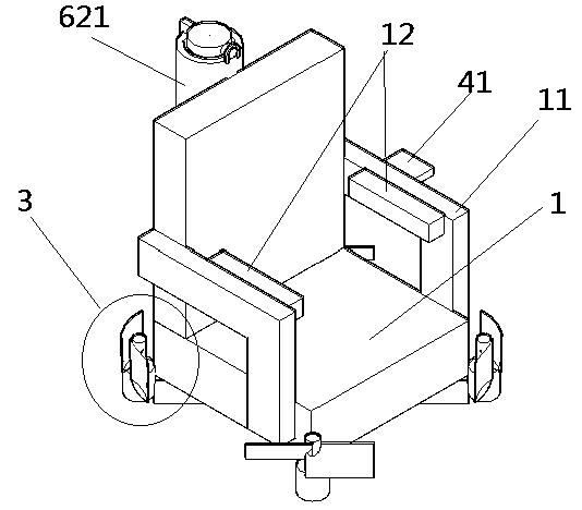
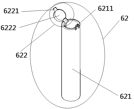
[0035] see Figure 1 to Figure 6 , a direction-controllable parachute chair, comprising an ejection chair 1, a telescopic shaft 2, an electric lift device 3, a controller 4, a battery 5 and a parachute throwing device, the parachute throwing device including a detection device 61, an ejection device 62 and a parachute 63.

[0036] Both sides of described ejection chair 1 are provided with armrest 11; Described armrest 11 inner side is provided with safety airbag 12, and the safety airbag 12 of left armrest 11 and right handrail 11 can be seated on the people's abdomen of ejection chair 1 after expanding. pack.

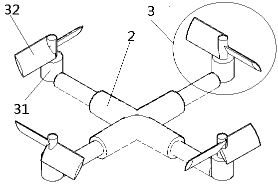
[0037] The telescopic shafts 2 are provided with four, and the four telescopic shafts 2 are arranged symmetrically under the ejection chair 1 at the same height. In this embodiment, the four telescopic shafts 2 are arranged in an X shape, and in other embodiments, the four telescopic shafts 2 may also be arranged in a cross or in parallel. The telescopic shafts 2 in...


PUM


Abstract

The invention relates to a landing chair controllable in direction and relates to the field of aviation safety. The landing chair comprises an ejection chair, telescopic shafts, electric lift devices,a controller, a battery and an umbrella throwing device. The umbrella throwing device comprises a detection device, an ejection device and a parachute. The four telescopic shafts are symmetrically arranged below the ejection chair in the same height. The electric lift device is arranged at the tail end of each telescopic shaft. The controller is arranged inside the ejection chair, and the electric lift devices and the telescopic shafts are both electrically connected with the controller. The battery is arranged inside the ejection chair and supplies energy for the controller, the electric lift devices and the telescopic shafts. The detection device is arranged on the ejection chair and is connected with the controller. The ejection device comprises an ejection cylinder, a locking piece and an elastic piece, wherein the locking piece is arranged at the upper end of the ejection cylinder, and the elastic piece is arranged in the ejection cylinder. The parachute is arranged between the elastic piece and the locking piece, and the parachute is connected with the ejection chair at multiple points through a plurality of ropes. The landing chair can reduce the influence of the wind direction, and a pilot can manually control the landing chair to rapidly land on the designated ground after an air accident occurs.

Description

technical field [0001] The invention relates to the field of aviation safety, in particular to a direction-controllable landing chair. Background technique [0002] At present, most of the escape equipment used by aircraft when an air crash occurs is a parachute. On special aircraft such as some fighter jets and transport aircraft, ejection chairs are generally equipped so that the pilot can escape in time when an accident occurs. Traditional ejection chairs are often equipped with a parachute, but the parachute is greatly affected by the wind direction. After the pilot parachuted, he floated with the wind. The uncertainty of the landing location led to the ground rescue forces often needing to spend considerable effort to find the pilot. The parachute used in the first stage takes a long time in the landing process, and the air resistance suffered cannot be controlled. The above two major problems have led to the increase of rescue search difficulty and the long rescue tim...

Claims


Application Information

Patent Timeline
Patent Type & Authority Applications(China)
IPC IPC(8): B64D17/70B64D17/78B64D25/112
CPCB64D17/70B64D17/78B64D25/10
Inventor 王志成
Owner FOSHAN SHENFENG AVIATION SCI & TECH
Why Eureka
Try Eureka